Caliper details
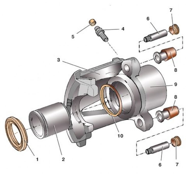
1 - protective cap; 2 - piston; 3 - support; 4 - air release valve; 5 – a protective cap of the valve; 6 - guide pin; 7 - protective cap; 8 - bushing; 9 – caliper cylinder; 10 - sealing ring
Removing the piston from the caliper cylinder
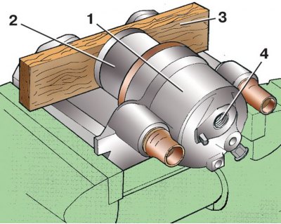
1 - support; 2 - piston; 3 - wooden gasket; 4 - hole for supplying brake fluid
O-ring removal
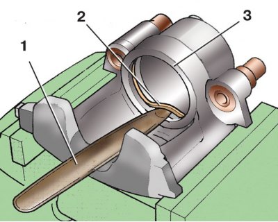
1 - scapula; 2 - sealing ring; 3 - caliper cylinder
Installation of a protective cap on the piston
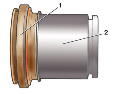
1 - protective cap; 2 - piston
Installing the piston in the caliper cylinder
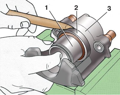
1 - piston; 2 - protective cap; 3 - caliper cylinder
1. Remove the wheel by first loosening the bolts of its fastening on the car standing on the ground.
2. Turn away a hollow bolt of fastening of a tip 7 (see fig. Front brake type FS III) brake hose to caliper. Having disconnected a brake hose, muffle its opening.
3. Remove the protective caps of the 5 guide pins.
4. Unscrew both guide pins 4.
5. Remove caliper 3 from steering knuckle 8.
6. Remove brake pads 1 and 2 from the caliper 3. If the pads do not need to be replaced, mark them so that they can be reinstalled later. During operation, the pads wear in, so if you swap them, braking will be uneven.
7. Carefully, so as not to damage, remove the edge of the protective cover 1 (see fig. Caliper details) from the cylinder groove 9.
8. Clamp caliper 1 (see fig. Removing the piston from the caliper cylinder) in a vise with soft metal pads on the jaws. Place a piece of wood 3 to prevent damage to the piston 2 when it is removed from the cylinder.
9. By supplying compressed air to the caliper cylinder 1 through the hole 4 for supplying brake fluid, squeeze out the piston 2. Remove the wooden gasket 3 and finally remove the piston 2 from the cylinder.
10. Remove protective cap 1 (see fig. Caliper details) from the piston 2. Replace the torn, cracked or loose cap 1.
11. With a wooden or plastic spatula 1 (see fig. O-ring removal), in order not to damage the mirror of cylinder 3, remove the sealing ring 2 from the groove of the cylinder.
12. Examine the mirror of cylinder 9 (see fig. Caliper details) and piston 2. If there are deep scratches, scratches, roughness, etc. replace the caliper assembly.
13. Rinse thoroughly with alcohol and dry piston 2 and cylinder 9 with compressed air.
14. Replace bushings 8 with torn or rubber that has lost its elasticity.
15. Lubricate piston 2 and new O-ring 10 with grease G 052 150 A2 or brake fluid.
16. Install the O-ring 10 into the groove of the cylinder 9.
17. Turn the protective cap 1 inside out (see fig. Installation of a protective cap on the piston) and put it on the back of the piston 2.
18. Insert piston 1 (see fig. Installing the piston in the caliper cylinder) into cylinder 3 and install the outer edge of the protective cap 2, turning it back into the groove of cylinder 3.
19. Press piston 2 (see fig. Pushing the piston into the cylinder) into cylinder 1 using special tool 3, while the inner edge of the protective cap must fit into the groove of the cylinder. In the absence of a device, this can be done, for example, with a wooden hammer handle. Press the piston evenly at different points around the entire circumference, making sure that the piston does not warp.
20. Install the caliper in reverse order. When connecting the brake hose, pay attention - under the tip 7 (see fig. Front brake type FS III) hose must be fitted with an O-ring.
21. Bleed the brake system (see subsection 9.9.6).
