Location of the air conditioning fan control unit
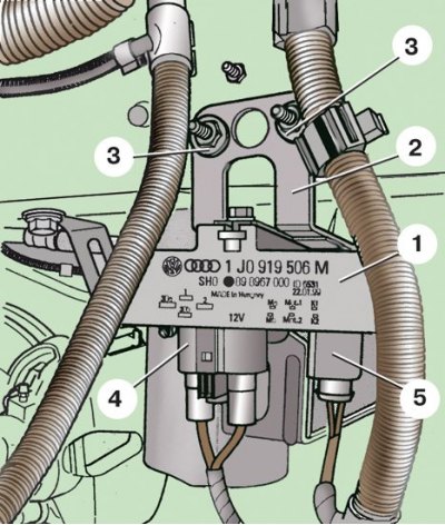
1 - control unit; 2 - bracket; 3 - nut; 4, 5 - connecting blocks
Removing the wire and lines from the holder
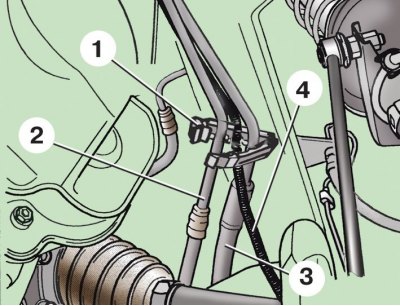
1 - holder; 2 - return line; 3 - pressure line; 4 – a wire of the gauge of the amplifier of a steering
Connection blocks of the pump unit
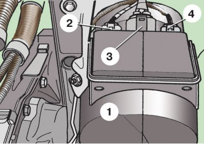
1 - pumping unit in an elastic casing; 2 - CAN-BUS connector block; 3 - power connector block; 4 – connecting block of wires of the gauge of the amplifier of a steering
Connection of lines to the pump unit
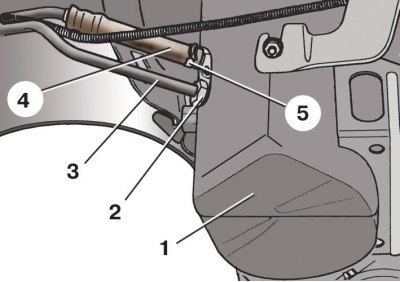
1 - pumping unit in an elastic casing; 2 - nut; 3 - pressure line; 4 - return line; 5 - clamp
Mounting the pump unit on the car
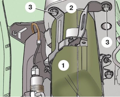
1 - pumping unit in an elastic casing; 2 - bracket; 3 - bolts
Pump unit with bracket, complete
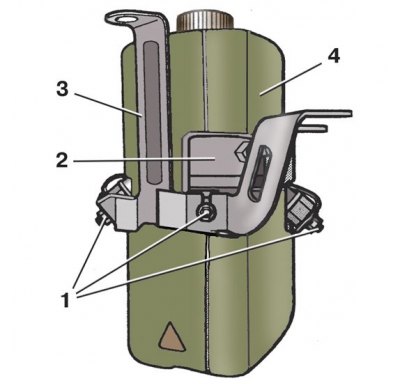
1 - nuts; 2 - pumping unit; 3 - bracket; 4 - elastic casing
Parts of the pumping unit
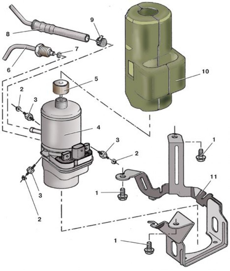
1 - bolt; 2 - nut; 3 - support; 4 - pumping unit; 5 – receiver cover; 6 - pressure line; 7 - sealing ring; 8 - return line; 9 - collar; 10 - elastic casing; 11 - bracket
The pump unit consists of a gear pump with an electric motor, a control unit and a receiver.
Attention! The pump unit cannot be repaired; in the event of a malfunction, it must be replaced as an assembly.
Examination
1. Raise and secure the front of the vehicle.
2. Remove the left front wheel.
3. Remove the front left wheel well cover.
4. Start the engine.
5. Check by ear and touch the operation of the pump unit 1 (see fig. Elements of the hydraulic power steering). Turn the steering wheel as far as it will go if necessary.
6. If the pump unit does not work, check the electrical circuits (see subsection 8.5.6).
7. A more thorough check of the pump can be carried out at a service station using special instruments.
8. Replace the failed pump unit.
9. Reinstall the locar and wheel.
Replacement
1. Disconnect the wire from the terminal «-» battery. Parts of car battery holder (bigger size) closes the receiver cover. In this case, remove the battery and its holder (see subsection 10.2).
2. Remove the air filter if necessary (see subsection 4.1).
3. Unscrew cover 9 (see fig. Elements of the hydraulic power steering) receiver and use a rubber bulb to remove the working fluid from the receiver through the filler neck.
4. Raise and secure the front of the vehicle.
5. Remove the left front wheel.
6. Remove the front left wheel well cover.
7. Remove the mudguard.
8. On models with an air conditioning fan control unit, disconnect two blocks 4 and 5 from the unit (see fig. Location of the air conditioning fan control unit) with wires, unscrew two fastening nuts 3 and remove bracket 2 with block 1.
9. Press the spring latch and open the holder 1 (see fig. Removing the wire and lines from the holder). Remove pressure 3 and return 2 lines from it, as well as wire 4 of the power steering sensor.
10. Place a container under the pump unit to collect the liquid that will flow from it when removed.
11. Disconnect from the pump unit 1 blocks 2 (see fig. Connection blocks of the pump unit), 3 and 4 with wires.
12. Open clamp with pliers 5 (see fig. Connection of lines to the pump unit) and carefully disconnect the return line 4 from the fitting of the pump unit.
13. Unscrew the fastening nut 2 and disconnect the pressure line 3 from the pump unit.
14. Plug the openings in the lines.
15. Loosen three screws 3 (see fig. Mounting the pump unit on the car) fasteners and remove the bracket 2 with the pump unit 1 in the elastic casing.
16. Loosen three nuts 1 (see fig. Pump unit with bracket, complete) fasteners and remove from the bracket 3 the pump unit 2 in the elastic casing 4.
17. Unfasten elastic cover 10 (see fig. Parts of the pumping unit) and remove the pump unit 4 from it.
18. Turn out three rubber support 3. Replace support with the torn, exfoliated or lost elasticity rubber.
19. Install the new pump unit in reverse order, replacing the pump unit bracket mounting bolts with new ones.
20. Replace the sealing ring 7 of the pressure line tip.
21. After that, fill the hydraulic system with working fluid and remove air from it (see subsection 8.5.10).
Tightening torques, Nm
| Rubber feet | 7 |
| Nuts for fastening the pump unit on the bracket | 7 |
| Nut for fastening the pressure line to the pumping unit | 30 |
| Bolts of fastening of an arm of the pumping unit to a body | 20, then turn 90° |
| Wheel bolts | 120 |
