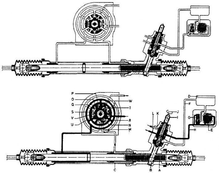
The principle of operation of the steering gear with rack and pinion and hydraulic booster (top - rotary annular valve in neutral position, bottom - rotary annular valve in working position - handlebar turned)

A - gear rack; In – a gear wheel of the steering mechanism; C - working cylinder; D - oil equalization tank; E - vane pump; F - return pipeline; G - valve with oil flow limiter; H - high pressure pipeline; I - the inside of the control box; J - rotating rod; K - radial groove I; L - radial groove II; M - rotating sleeve; N - guide sleeve; O - inlet groove; P - inlet groove; 0 - axial groove; R - axial groove; S - return clearance; T - return groove; U - return gap; V - partition; W - control clearance
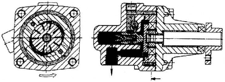
The principle of operation of the vane pump (pressurized power steering oil)

The effect of steering boost depends on the torque of the torque element on the steering gear. The greater the force required to turn the rudder, the greater the twisting of the torsional element, and the greater the given elastic deformation, the greater the amplifying effect.
The principle of power steering is to bypass special oil to the left or right side of the piston connected to the tie rod rack. The oil helps to move the piston, and therefore the rack, pressing on the corresponding side with a proportional amount of oil that passes through the system of bypass radial and axial channels - grooves - the holes open due to the twisting of the steering element.
The distributor and oil dispenser is a very precise system located in the control box in the gear area. From there, the oil enters through the high pressure pipeline into the working cylinder formed in the cavity of the horizontal part of the steering. A rod passes through the middle of the cylinder, passing on the left side into the steering rack. In the middle of the rod is a narrow piston. It is well sealed with the working surface of the cylinder. On the sides, the rod slides in plain bearings, also well sealed. At the protruding ends of the rail there are horizontal ball joints with steering rods (see fig. The principle of operation of the steering gear with rack and pinion and hydraulic booster).
In addition to the steering itself, the system also includes an independent oil pump and an oil surge tank. The connection between the pump and the steering is made by two pipelines, which are a combination of steel pipes and high pressure hoses. Pipelines are not dismantled. Connection between surge tank and pump, thus suction and return pipes (it means between reservoir and steering), are low pressure pipelines.
The oil pump for the power steering is the so-called vane. In principle, this is an oval-shaped cavity in which a shaft rotates with several nested axially spring-loaded sealing plates. When turning, the volume of the chambers, always formed by two adjacent plates and a segment of the working surface of the cavity, changes. Thus, when the shaft rotates, oil is sucked in on one side, and squeezed out on the other side (see fig. The principle of operation of the vane pump (pressurized power steering oil)). The pump produces an amount of oil per minute in the range of 0.3–1.7 cubic meters. dm at a pressure of 7 to 13 MPa (maximum pressure 20 MPa) according to turnover. The pump operates in the speed range from 500 to 7000 1/min. It is driven by a multi-ribbed belt, along with the alternator, and sometimes the air conditioning compressor, from an external crankshaft pulley.
The power steering is also active when the steering oil pump is not working, i.e. with the engine off. Of course, then the force required to turn the steering wheel increases significantly, because. amplifier is not working. Similarly, as in the braking system with an amplifier.
