Exhaust Assembly - 1.6-55kW Engine

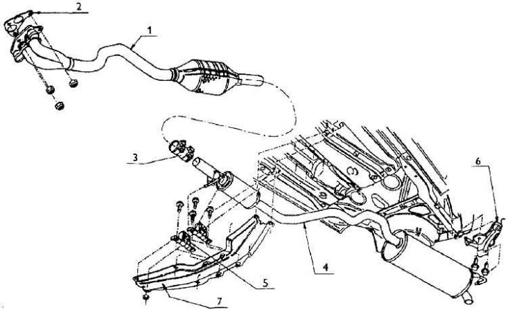
1 - the front of the exhaust; 2 - seal; 3 - clamp; 4 – a back part of an exhaust; 5 - front bracket; 6 - rear bracket; 7 - bearing structure of the exhaust
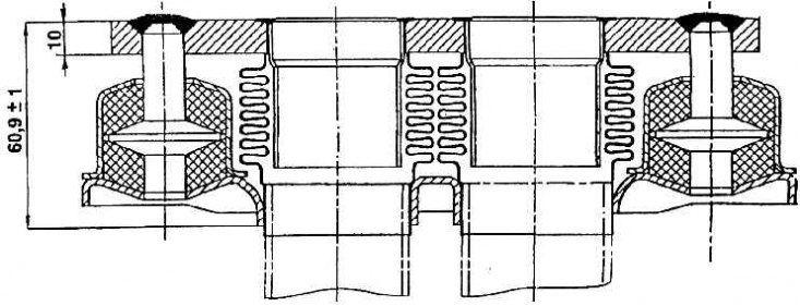
The principle of the technical solution of the elastic element of the front part of the exhaust pipeline

In vehicles with a 1.6–55 kW engine, the exhaust path consists of two parts. The front end is shaped to run under the engine as the exhaust manifold is on the front side of the engine (in the direction of travel). The front part of the exhaust is attached to the manifold flange with a 10 mm thick flange with three bolted connections. Between the flanges there is a metal seal made of three combined thin steel sheets, with a pre-embossed profile to seal around the round holes. The seal must be replaced with a new one after each disassembly. If the manifold flange has two channels, then the front part of the connected exhaust pipe consists of two pipes. Then they merge into one and a controlled catalyst is welded to it.
In order to ensure mutual oscillations of the engine and the exhaust pipeline, an elastic element is installed under the flange (see fig. The principle of the technical solution of the elastic element of the front part of the exhaust pipeline). Between the outlets from the flange and the connecting branches of the pipeline there is a gap covered by two bellows welded to both flanges. So-called vibration dampers are installed on the sides between the flanges. Vibration dampers consist of fingers with lenticular plates. The pins are welded to the top flange and inserted into cylindrical bodies welded to the bottom flange.
The voids are filled with steel fibers. This constructive solution allows the necessary vibrations to be produced, but protects the bellows from damage by the entire lower part of the pipeline accidentally torn off.
An oxygen probe bracket is placed in the pipeline in front of the catalyst (lambda). The catalyst itself, as already mentioned, is a trimetal (platinum, palladium and rhodium). A heat shield is welded to the bottom of the catalyst, which protects the chassis from heat radiation.
A heat shield is also attached above the entire exhaust system under the floor.
The rear exhaust front pipe connects to the catalytic converter outlet pipe and is well sealed with a two piece clamp clamp. The position of the clamp is determined by the marks on both parts, and there is also a certain gap between the ends of the tubes. Behind the clamp is an expansion chamber.
In front of the expansion chamber, a bracket is welded onto the pipeline with two fingers inserted into a rubber-metal socket screwed to the body.
The exhaust ends with an oval-section muffler, from which a figured tube emerges, bent by the outlet to the chassis. On the rear side of the muffler there is a hook inserted into a rubber-metal block screwed to the body. This is the second fastening element that allows relative oscillation of the exhaust assembly.
Neither the entire exhaust nor any part of it may be replaced by an exhaust of a different design. Individual parts can also be changed independently, but only for parts of the same order number.
