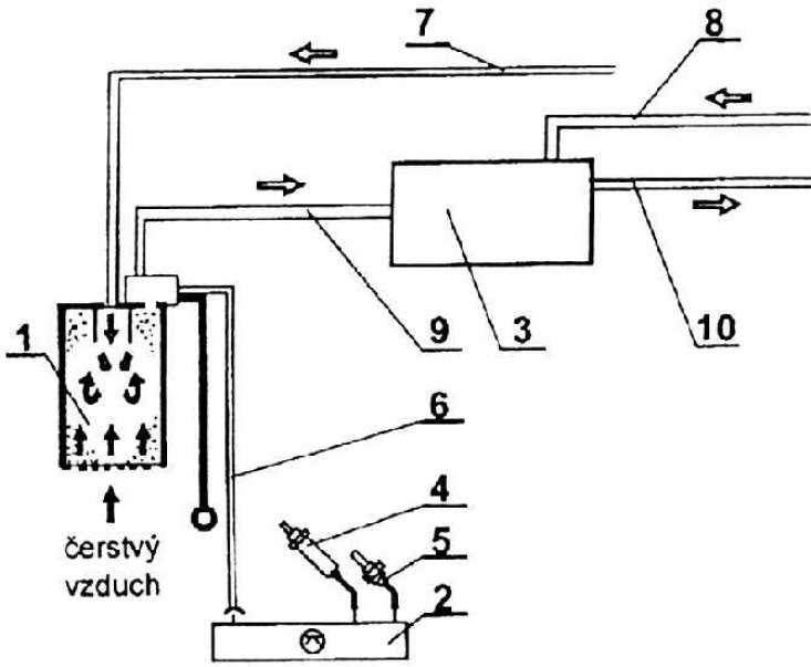
Deaeration scheme (Gas engine)

1 - a tank with activated carbon and a solenoid valve; 2 - control unit; 3 - fuel injection system; 4 - oxygen probe (lambda); 5 - coolant temperature sensor; 6 - electrical connection of the electromagnetic valve to the control unit; 7 - ventilation of the fuel tank; 8 - fuel supply to the injection system; 9 - connection of the tank with activated carbon through the solenoid valve with the fuel injection system; 10 - drain fuel line; the arrow indicates the direction of fresh air
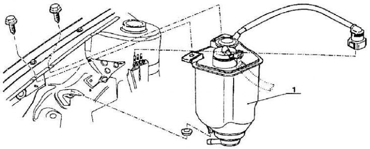
Activated carbon tank and its mounting (gasoline powered vehicles)

1 - a tank with activated carbon
The deaeration system with activated carbon tank is normally closed. When gasoline is heated, the resulting vapors enter the activated charcoal tank. There they undergo regeneration due to the fresh air sucked in due to rarefaction through a solenoid valve. The fuel captured by the activated carbon is returned to the suction pipe for subsequent combustion. The solenoid valve is controlled by the fuel system and ignition system control unit.
It all works as follows: while there is no voltage at the terminals of the solenoid valve, the valve is open for bypass even with a slight vacuum. (The deaeration solenoid valve can only be in working condition when the ignition is on). When voltage is applied to the solenoid valve coil, the valve closes. The opening duration is controlled by the control unit, which evaluates the signal from the throttle opening angle sensor and the signal from the oxygen probe (lambda). At engine operating temperatures below 60°C, the valve remains closed. The solenoid valve is part of the activated carbon tank.
Valve operation: the locking spring presses the armature with the seal into the seat. The bypass is also closed under vacuum. When the control unit gives a pulse to the valve coil winding, the armature will be attracted, overcoming the resistance of the spring, the valve will open, and fuel vapors can enter the engine from the activated carbon tank.
