Note: 2 rods -T10486/1- are included in the set of tool -T10486-. If the company has tool -T10486-, only two more rods -T10486/1- are needed. Tool -T10486 A- contains 4 guide rods -T10486/1- and 2 guide rods -T10486/2-.
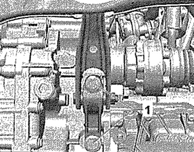
Remove the noise-insulating casing, Unscrew the bolts -1- of the lower support of the power unit.

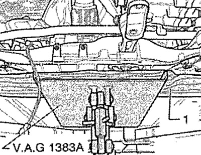
Position engine and gearbox jack -VAG 1383A- under subframe. Place wooden block -1- between jack -VAG 1383A- and subframe.

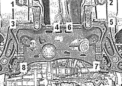
Release screws for supports -1- and -2-. To fix the position of the subframe, screw in the guide pins one after the other at points -3-, -5-, -7- and -8-.

Note: The special tools -T10486/1- must be tightened to a maximum torque of 20 Nm, otherwise the threads may be damaged.
Remove bolt -3- and replace with pin -T10486/1-, tighten to 20 Nm. Unscrew bolt -5- and replace with pin -T10486/1-, tighten to 20 Nm. Unscrew bolt -8- and replace with pin -T10486/1-, tighten to 20 Nm. Unscrew bolt -7- and replace with pin -T10486/1- tighten to 20 Nm. Now the position of the front suspension is fixed. If it is not possible to insert the pins -T10486/1- into the corresponding holes in the subframe, proceed as follows: Finish the hole in the lower subframe, eg with a file, so that the pins -T10486/1- can be inserted into the holes. Treat matched holes with corrosion protection, eg zinc spray -0 007 500 04-.
Installation
Installation in reverse order. Replace pins -T10486/1- one by one with new bolts. Tighten the screws to the specified tightening torque. Carry out a test drive. Check the position of the steering wheel during a test drive.
Note: If the steering wheel is turned after a test drive in a straight-line direction of travel, the wheel alignment must be adjusted.
Tightening torques

