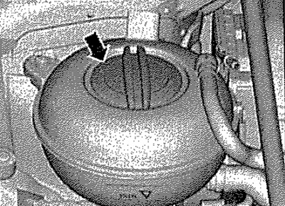
Note: If the engine block was replaced when the engine was removed, then tighten the injector pressure plates to the specified torque when installing the new engine block. The engine is removed together with the gearbox down. During installation, all cable ties should be placed in their original positions. During installation, install all heat-shielding cuffs in their places. Danger of burns from hot steam and hot coolant. When the engine is hot, the fluid in the cooling system is under pressure. To relieve pressure, cover the expansion tank cap with a rag and carefully unscrew, gradually relieving pressure.
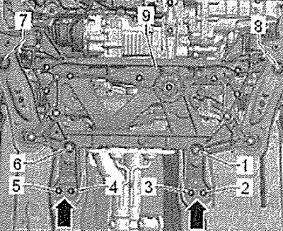
Remove subframe -9- without steering gear.
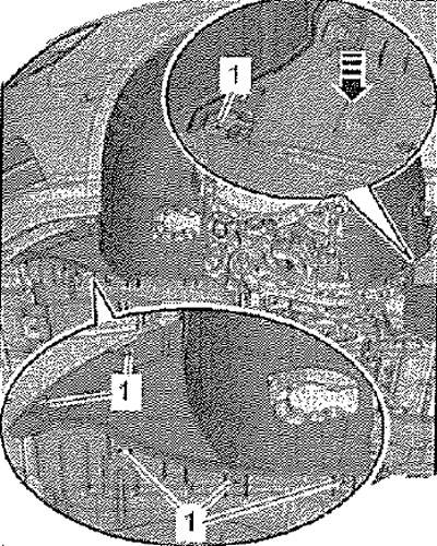
Remove the front left and right fender liner. Drain coolant. Remove engine cover.
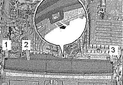
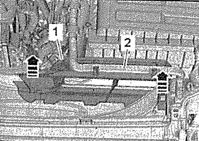
Remove bolts -1.3-. Release catch -arrow- and remove cover -2-.
Release coolant hose -2-. Unlock retainers -arrows- and remove top part -1- of air duct.
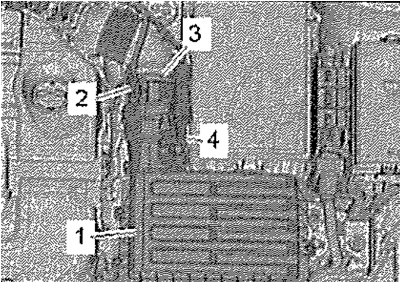
Disconnect electrical connector -2- from mass air flow meter -G70-. Detach vacuum hose -4-. Loosen hose clamp -3- and remove air hose. Remove air cleaner housing -1-.
Unscrew left and right screws -arrow-. Unhook and remove bottom part -1- of air duct.
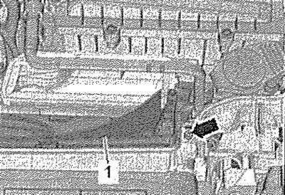
Remove battery holder -1-.
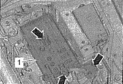
Detach hose -1- for crankcase breather from cylinder head cover by pressing hose clips. Unclip vacuum hoses -arrows- at breather pipe. Unscrew screw -2-, move air duct with intake manifold connection to rear and detach from turbocharger. Position -3- is ignored.
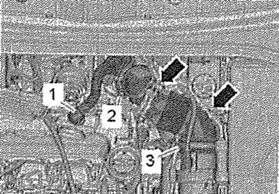
Disconnect vacuum hose from turbocharger vacuum drive. Detach vacuum hose -1- from T-piece.
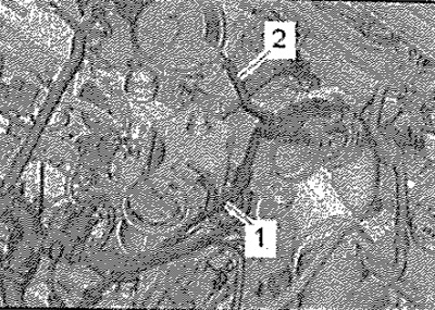
Unlock catch -arrow-, disconnect vacuum hose -1-. Position 2, 3 - ignore.
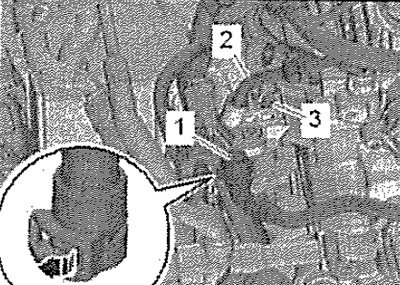
If present: Remove heat shield. Raise retaining clips -arrows- and detach coolant hoses from heater heat exchanger.
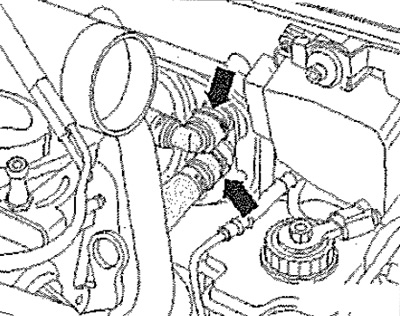
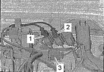
Disconnect connectors and release wiring harnesses.
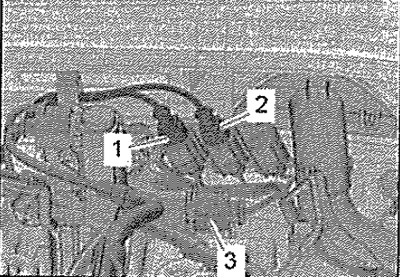
1. Exhaust gas temperature sender 4 -G648-
2. Exhaust gas temperature sender 3 -G495-
Remove electrical connector -3- for lambda probe from bracket -G39-, disconnect and move electrical cable clear.
Vehicles with auxiliary heater
Remove heat shield -2-. Loosen clamp -1- and remove coolant hose.
All
Disconnect electrical connector -5- from fuel temperature sender -G81-.
Attention! Risk of burns from hot fuel. The temperature of the fuel lines and fuel after the engine is turned off can reach WOT. Allow the fuel to cool before disconnecting the fuel lines as there is a risk of severe burns. Use protective gloves. Wear safety glasses.
Loosen clamps -4, 6-, remove pressure and return hoses-fuel lines. Loosen clamps -1, 3- and detach coolant hoses. Remove screw -2-.
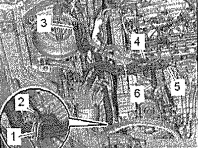
Disconnect fuel line -2- and collect escaping fuel with a rag. Unlock and disconnect the quick coupler.
Vehicles with cooling radiator versions 1 and 2
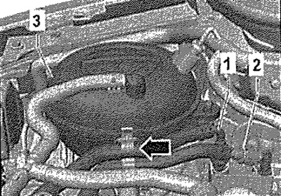
Raise retaining clip -arrow-, disconnect upper right coolant hose from charge air cooler.
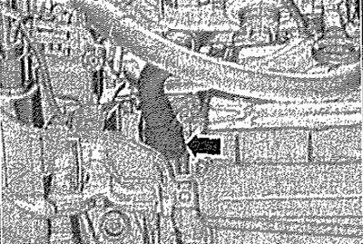
All
Raise retaining clip -arrow- and disconnect upper left coolant hose from radiator.
Note: For the following operations for loosening the clips, use the door trim puller -MP8-602/1-.
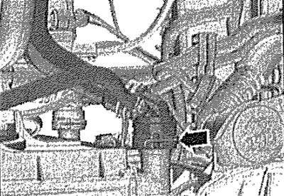
Disconnect connector -2- from engine control unit -J623-. Remove from holder and disconnect connectors -1, 3, 4-. Hang wires.
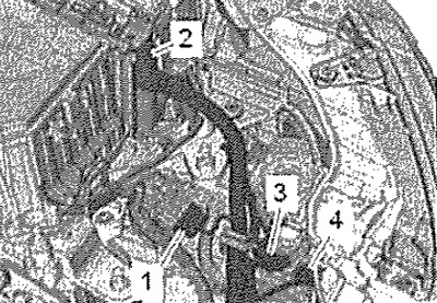
Unlock catches -arrows-, remove cover -1- for electronics box in engine compartment.
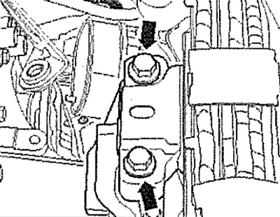
Use a screwdriver to unlock the catch -arrow- and remove the cover -1- of the electronics box in the engine compartment towards the top.
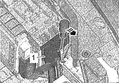
Unscrew nut -arrow-, disconnect and hang cable.
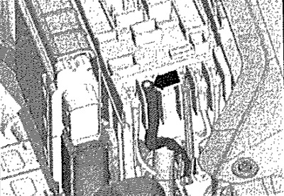
Vehicles with manual gearbox
Disconnect connector -2-. Unscrew the protection of the B+ pole -1- and disconnect the B+ wire from the starter solenoid relay. Unscrew nut -3- and remove ground wire.
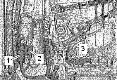
Disconnect electrical connectors at front left from gearbox.
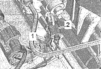
1. Gearbox neutral position sender -G701-
2. Reversing light switch -F4-
Remove the selector and shift cable ties from the gearbox, unscrew the cable supports and set aside together with the cable ties.
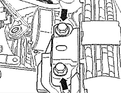
Vehicles with manual gearbox 0A4
Remove the clutch slave cylinder and lay it aside with the combination pipe connected. Unscrew bolts -arrows- for gearbox support by approx. 2 turns.
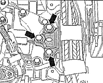
Vehicles with manual gearbox 02Q
Disconnect the combination pipe from the bleeder port of the slave cylinder. Unscrew bolts -arrows- for gearbox support by approx. 2 turns.
Vehicles with DSG 0CW gearbox
Disconnect connector -3-. Unscrew the protection of the B+ pole -2- and disconnect the W wire from the starter solenoid relay. Unscrew nut -4- and remove ground wire.
Carefully! Risk of failure of the control unit (Mechatronik) due to static discharge. Do not touch the contacts of the gearbox connector with your hands.
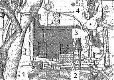
To remove a static charge, touch with your hand (without gloves) vehicle mass. Unplug connector -1- of mechatronic unit DSG gearbox -J743- by turning the cam lock counterclockwise. Remove the selector cable from the gearbox, unscrew the cable support and tie it higher together with the selector cable. Unscrew bolts -arrows- for gearbox support by approx. 2 turns.
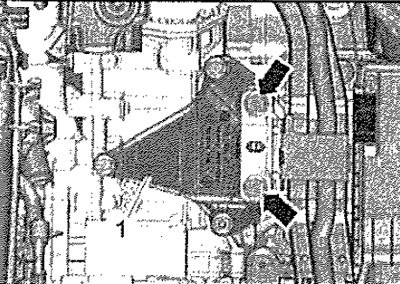
Vehicles with DSG 0D9 gearbox
Remove the selector cable from the gearbox and remove it from the cable support. Disconnect connector -2-. Unscrew the protection of the B+ pole -1- and disconnect the B+ wire from the starter solenoid relay. Disconnect ground wire from body. To remove a static charge, touch with your hand (without gloves) vehicle mass. Unplug connector -4- of mechatronic unit DSG gearbox -J743- by turning the cam lock counterclockwise.
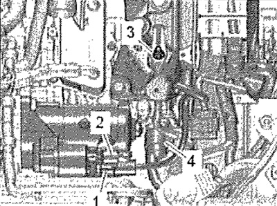
Loosen screws -2- for gearbox support by approx. 2 turns. -Position 1, A- ignore.
All
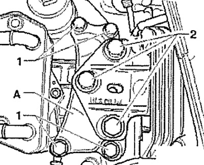
Loosen screws -arrows- for engine support by approx. 2 turns.
Vehicles with auxiliary heater
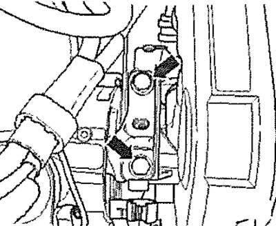
Loosen clamp -1-, unscrew nut -2-, remove auxiliary heater muffler.
All
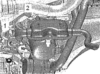
Remove poly V-belt. Unplug connector -1- at air conditioner compressor pressure regulator -N280-.
Carefully! Risk of damage to compressor and refrigerant hoses. Do not stretch, bend or kink pipes and refrigerant hoses.
Remove screws -arrows-.
Attention! Do not open the refrigerant circuit of the air conditioner.
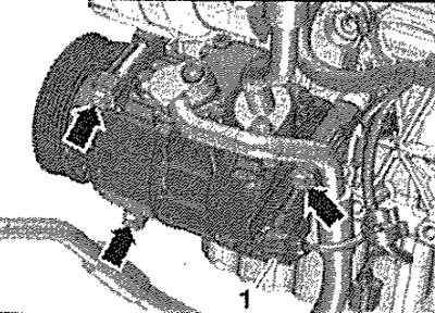
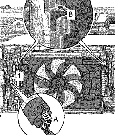
Detach the air conditioner compressor with hoses connected from the bracket and hang it on the right side. Unplug electrical connector -1- for radiator fan, to do this push catch -arrow A- backwards and unlock downwards. Simultaneously press the tabs on the fan frame -arrow B- on the left and right and remove the fan frame from the radiator towards the bottom.
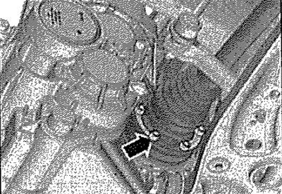
Remove left and right drive shafts -arrow- from gearbox and tie up at rear.
Note: When removing, take care not to damage the protective coating on the drive shaft.
Disconnect electrical connector -1- from exhaust flap control unit -J883-. Release clutch -2- and push back.
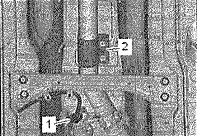
Remove screw -2- and remove clamping collar. Remove intake pipe. -Position 1-ignore.
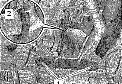
For vehicles with engine code CRKB
Detach left underbody trim in middle towards exhaust pipe and press downwards. Pull electrical connector -arrow- for lambda probe downstream of catalytic converter -G130- out of holder, unplug and move electrical cable clear.
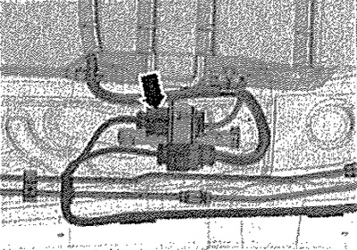
All
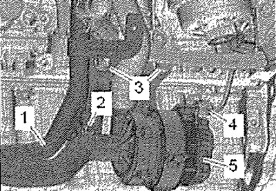
Disconnect connector -4-. Remove nut -2- and screws -3-. Press coolant pipe -1- and charge air cooling pump -V188- -pos. 5-.
Instruction. Various executions depending on modification.
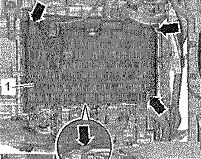
Loosen fasteners -arrows- and remove noise insulation -1- from sump.
Vehicles with all-wheel drive
Mark position of propshaft coupling and bevel gear flange relative to each other.
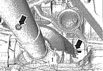
Unscrew propshaft from bevel gear -arrows- while holding triangular flange with a spudger.
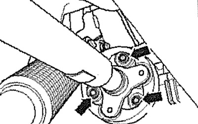
Slightly move the power unit forward (to the front of the body) and disconnect the cardan shaft from the angular transmission.
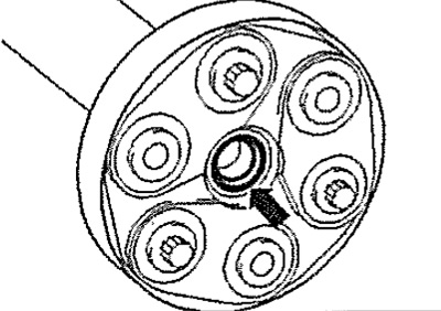
Attention! Risk of damage to O-ring -arrow- of propshaft flange. Press propeller shaft horizontally as far forward and to the right as possible (to the right side of the vehicle). If the sealing ring is damaged, the cardan shaft must be replaced.
All
Screw engine bracket -T10497- with pins -T10497/1- to cylinder block with screw -1- to approx. 20 N.m using upper oval hole "D". Attach engine and gearbox jack -VAG 1383 A- to engine support -T10497- and raise power unit slightly.
Note: Unscrew the bolts of the power unit supports from the ladder.
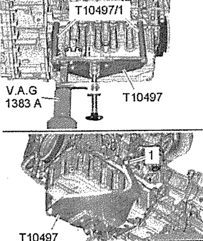
Completely unscrew bolts -arrows- for engine support.
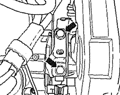
Completely unscrew bolts -arrows- for gearbox support.
Note: Depending on KP-2 or 3 bolts. Shown as an example is a gearbox support for vehicles with an OCW dual-clutch gearbox. Risk of damage to vacuum hoses and electrical wires, as well as parts of the engine compartment. Check that all vacuum lines and electrical wires connecting the engine, gearbox and body are disconnected. When lowering the power unit, remove it from the engine compartment with caution.
The power unit has been removed.
