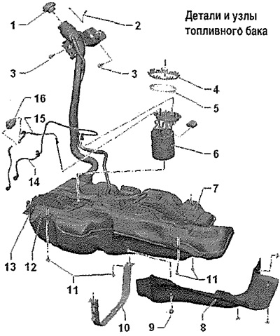
1. Filler cap: when properly installed, a characteristic click should be heard; suspended from the filler hatch assembly
2. Ground wire: filler neck; for dissipation of electrostatic charge
3. 8 Nm: replace
4. Ring nut, 110 Nm; loosen and tighten with the key -T30101 (3087) -
5. O-ring: replace; install dry
6. Fuel supply module; with built-in fuel filter, the filter cannot be replaced separately
7. Fuel tank
8. Heat shield: fuel tank
9. Clamping washer
10. Clamp: mark installation position before removing; ensure correct installation
11. 20 Nm + tighten by 90° (¼ vol.): replace
12. Bracket: for fuel pump control unit -J538-
13. Bracket: for vehicles with auxiliary heater; for metering pump -V54-; ensure the correct position of the dosing pump in the bracket holes
14. Fuel supply line: to the engine: fastened to the fuel tank with clamps: do not bend
15. Fuel line; for vehicles with autonomous heater; to metering pump -V54-; do not go too far
16. Metering pump -V54-: for vehicles with auxiliary heater
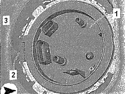
Mounting position of the fuel supply module

The marking -2- on the cover of the fuel supply unit -1- must be on the fuel tank opposite -arrow 3-.
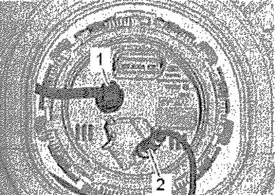
Connect fuel lines to fuel delivery module

1. Fuel supply line to the engine.
2. Fuel line to metering pump -V54-.
