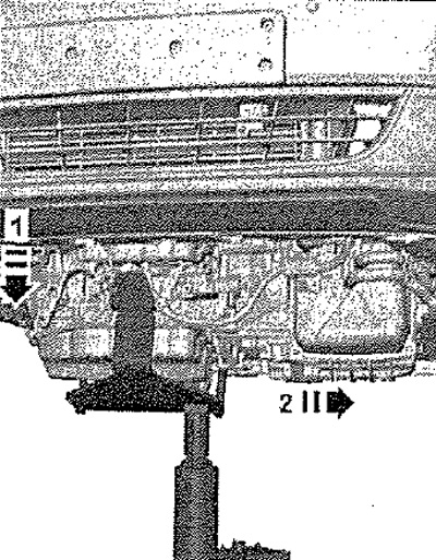
Note: The engine is removed downwards with the gearbox. All bandages released or cut when removing the engine must be reinstalled in the same places when installing the engine. When carrying out installation work, especially in the engine compartment due to its dense layout, the following regulations must be observed: pipelines of all types (fuel, hydraulic, adsorber, coolant, coolant, brake fluid, vacuum) and electrical wires must be laid as they were originally laid. To prevent damage to hoses, pipes or wires, sufficient clearance must be maintained to all moving or hot parts.
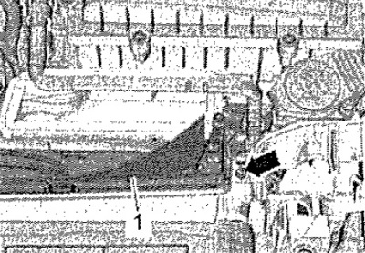
Drain coolant. Remove attachment bracket. Remove both front fender liner. Remove engine cover. Remove the air duct and air filter housing. Remove screws on right and left air duct -arrow-. Detach bottom part of air duct -1- from mountings and remove. Remove the battery and its bracket.
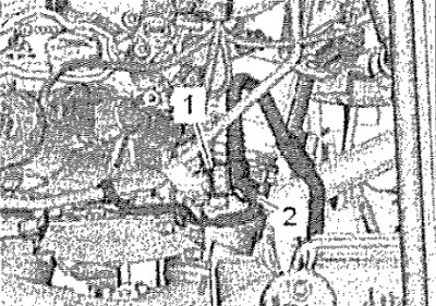
Detach vacuum hose -2-. Press the release buttons on the vacuum hose -1- and remove the hose from the vacuum pump.
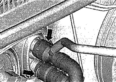
Raise clips -arrows- and disconnect coolant hoses from heater heat exchanger. Keep coolant hoses pointing downwards and allow coolant to drain.
Vehicles with auxiliary heater
Open clamp -1-, lift retaining clips -arrows- and detach coolant hoses.
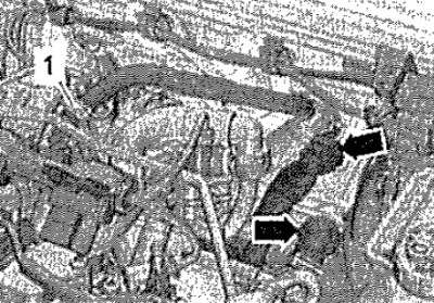
All
Remove connectors -1, 2- from the bracket and disconnect, release the wire.
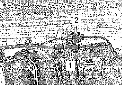
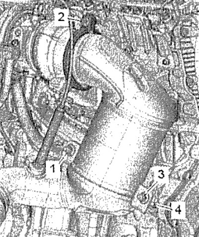
Unscrew screw -2- and remove screw clamp. Unscrew nuts -1, 3- and tie up catalytic converter to the body so as not to damage the bellows.
Note: Do not bend the bellows by more than 10°- risk of damage Pos. -4- can be ignored.
Detach hose couplings -1- and -2-. Detach hoses from coolant expansion tank -3-.
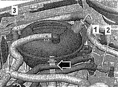
Loosen clamps -1 and 2- and detach coolant hoses.
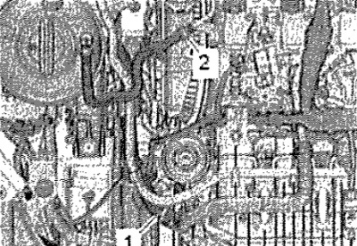
Raise clamp -arrow- and detach upper right coolant hose from radiator.
Note: In subsequent operations, use to release the spring clips. Door trim removal tool -MP8-602/1-.
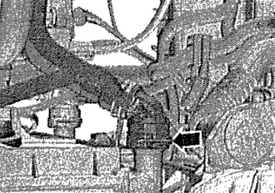
Disconnect connector -1- from engine control unit -J623-. Remove connectors -2, 3- from bracket and disconnect. Hang up the wiring harness.
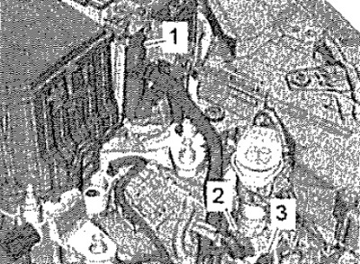
Unlock catches -arrows- and remove cover -1- for electronics box in engine compartment.
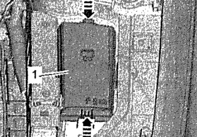
Unlock catch -arrow- with a screwdriver and remove switch box cover -1- towards top.
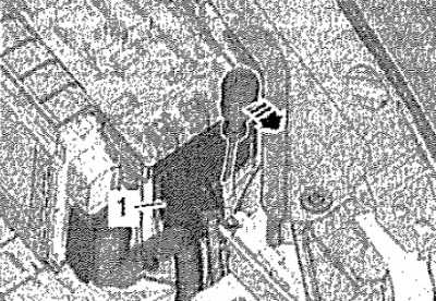
Loosen nut -arrow-, detach and hang cable.
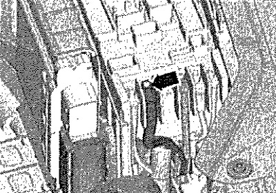
A/ms MCP 02S
Disconnect connector -2-. Turn back the protective collar of the B + -1 - pole and unscrew the B + wire from the starter traction relay. Unscrew nut -3- and remove ground wire.
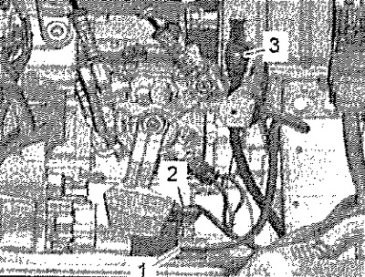
Disconnect front left connectors from gearbox.
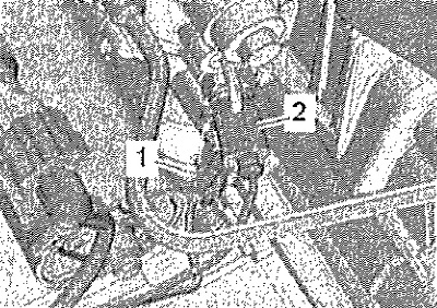
1. Gearbox neutral position sender -G701-.
2. Reversing light switch -F4-.
Remove the shift cable and guide cable from the gearbox and set aside. Remove the slave cylinder.
Carefully! Risk of damage to the clutch slave cylinder. After disconnecting the clutch slave cylinder with the combined pipe, do not press the clutch pedal.
Vehicles with automatic transmission DSG 0CW
Disconnect connector -3-. Turn back the protective collar of the B+ pole -2- and unscrew the B+ wire from the starter solenoid relay. Unscrew nut -4- and remove ground wire.
Attention! Risk of failure of the control unit (Mechatronik) due to electrostatic discharge. Do not touch the contacts of the gearbox connector with your hands.
touch with hand (without gloves) conductive body part in order to discharge itself from an electrostatic charge. Unplug connector -1- from mechatronic control unit for DSG gearbox -J743-.
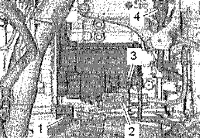
A/ms automatic transmission 0D9
Remove the selector cable from the gearbox and remove it from the cable support. Disconnect connector -2-. Turn back the protective collar of the B+ pole -1- and unscrew the B+ wire from the starter solenoid relay. Unscrew nut -3- and remove ground wire.
Note: In some versions, the ground wire is attached to the starter screw.
touch with hand (without gloves) conductive body part in order to discharge itself from an electrostatic charge. Unplug connector -4- of mechatronic unit DSG gearbox -J743- by turning the cam lock counterclockwise.
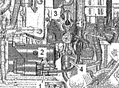
All
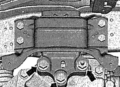
Unscrew bolts -arrows- for gearbox support by approx. 2 turns.
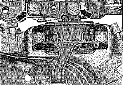
Loosen screws -arrows- for engine support by approx. 2 turns.
Loosen clamp -arrow- and detach air hose -1- from charge air cooler on left.
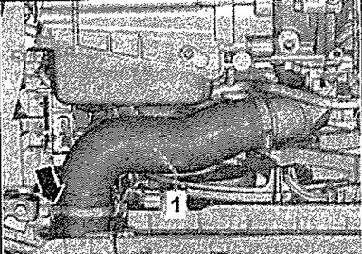
Loosen clamp -2- and remove air hose from intercooler on right. Pos. -1 - can be ignored.
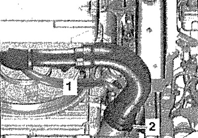
Seal open lines and connections immediately with clean plugs from the engine plug set, eg -VAS 6122-. Release coolant hose -3-. Remove screws -arrows-. Loosen clamp -2-. Disconnect connector -1- from charge pressure sender -G31-. Remove the right air pipe.
Vehicles with auxiliary heater
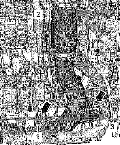
Loosen clamp -1-, unscrew bolt -2- and remove auxiliary heater muffler.
All
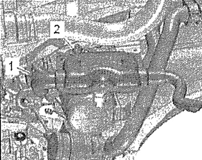
Attention! Risk of damage due to reverse running of a used V-ribbed belt. Before removing the V-ribbed belt, mark the direction of its running with chalk or a felt-tip pen.
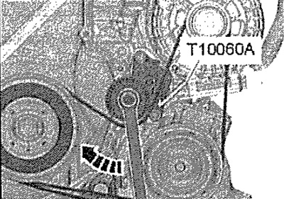
To loosen the poly V-belt, turn the tensioner clockwise -arrow-. Remove the V-ribbed belt from the air conditioner compressor pulley and loosen the tensioner.
Note: Ignore retainer -T10060A-.
Unplug connector -1- from air conditioner compressor regulating valve -N280-.
Attention! Risk of damage to the air conditioner compressor, pipes and refrigerant hoses. Do not stretch, bend or kink pipes and refrigerant hoses.
Remove screws -arrows-.
Attention! Do not open the refrigerant circuit of the air conditioner.
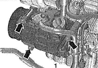
Detach the air conditioner compressor with hoses connected from the bracket and hang it on the right side. Remove left and right drive shafts -arrow- from gearbox and tie up at rear.
Note: Take care not to damage the protective coating on the drive shaft.
Vehicles with all-wheel drive
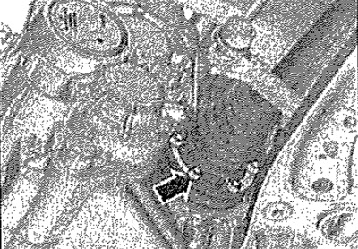
Loosen the screws - see arrows- and remove heat shield -1-. Mark position of propshaft coupling and bevel gear flange relative to each other.
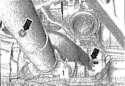
Unscrew propshaft from bevel gear -arrows- while holding triangular flange with a spudger.
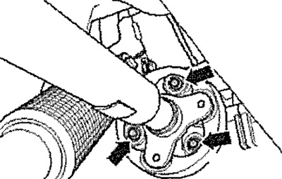
Slightly move the power unit forward (in the direction of travel) and disconnect the cardan shaft from the angular transmission.
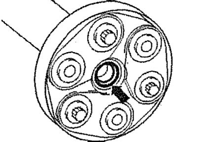
Carefully! Risk of damage to O-ring -arrow- of propshaft flange. Press propeller shaft horizontally as far forward and to the left as possible (to the left side of the vehicle). If the sealing ring is damaged, the cardan shaft must be replaced.
All
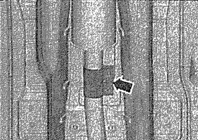
Release clutch -arrow- and push back. Remove catalytic converter with exhaust pipe.
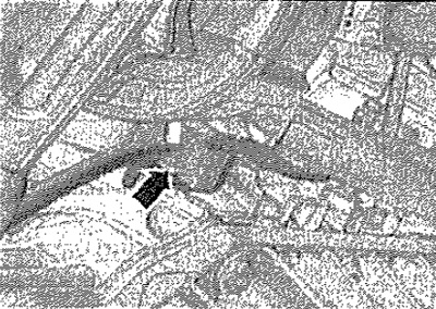
Unscrew bolt -arrow- and press bracket with wiring harness to one side.
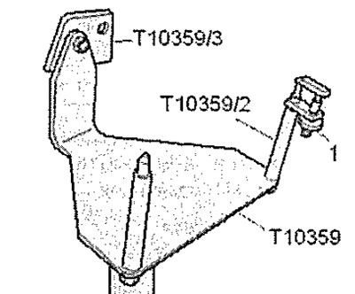
Screw adapter -T10359/3- to engine bracket -T10359- as shown. Screw pin -T10359/2- with locking element -1- from gearbox mounting -3282- to engine bracket.
Screw engine bracket -T10359- with screw -1- to cylinder block to 20 Nm and secure with locking piece -1- from engine bracket 3282-. Attach engine and gearbox jack -VAG 1383 A- to engine support -T10359- and raise power unit slightly.
Note: Unscrew bolts for power unit supports from ladder -WS 5085-.
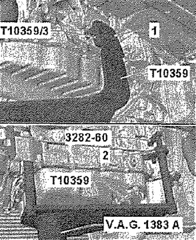
Completely unscrew bolts -arrows- for engine support. Completely unscrew screws -arrows- for gearbox support.
Attention! Risk of damage to vacuum hoses and electrical wires, as well as parts of the engine compartment. Check that all vacuum lines and electrical wires connecting the engine, gearbox and body are disconnected. When lowering the power unit, remove it from the engine compartment with caution.
Lower engine from gearbox -arrow 1-. Pos. -2- can be ignored.
