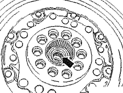
Note: Replace self-locking nuts during assembly work. Use new screws that are tightened to the specified tightening angle, as well as O-rings and seals. Secure all hose connections with clamps corresponding to the state of serial production. All bandages released or cut during removal must be reinstalled in the same places during installation. Check needle bearing - see arrow - in the crankshaft. If it is damaged or has a blue tint color (due to overheating), it needs to be replaced. Lightly lubricate the needle bearing - see arrow - and the axis of the drive shaft (not prongs) high temperature grease. Slightly lubricate the spline with a suitable lubricant.

Check whether balancing sleeves -A- are fitted to center the gearbox in the cylinder block, insert if necessary. When installing the gearbox, pay attention to the correct installation of the intermediate plate between the engine and the gearbox. Carefully raise gearbox on engine and gearbox jack -VAG 1383 A- and bring gearbox support -3282- into installation position. The gearbox is moved away from the engine by approx. 30 mm. Install the gearbox, while not clamping the wires and pipelines. Connect gearbox to engine. Install the selector lever cable to the gearbox.
Note: Do not kink or break the selector lever cable.
Install the machine support as follows: Insert the gearbox bracket -A- between the gearbox and the bearing bracket of the gearbox support. Secure gearbox bracket -A- with new screws -1- to gearbox. Slowly raise the box on the hooks of the holding device -MP9-200 (10-222 A) - to the bearing bracket of the gearbox support. Screw in new screws -2- and tighten by hand.
Carefully! Before screwing in the screws, the -2-gearbox console and the bearing bracket of the gearbox support must be absolutely parallel to each other, otherwise the threads will be damaged.
Detach gearbox support -3282- from gearbox.
Vehicles with all-wheel drive
Carefully! Risk of damage to O-ring arrow - propshaft flange. Press the power unit against the front wall of the plenum box and insert the trunnion of the transfer case into the propeller shaft flange.
Install driveshaft. Install transfer box bracket and tighten bolts
Vehicles with front wheel drive
Install the right flange shaft on the gearbox.
Further for all vehicles
Connect left and right drive shafts to gearbox flange shafts.
Vehicles with front wheel drive
Install right drive shaft guard on engine and tighten screws -arrows- to 35 Nm.
Vehicles with all-wheel drive
Fit heat shield for right drive shaft and tighten nuts -arrows*.
Further for all vehicles
Install the attachment bracket. If fitted, install front left vehicle level sender -G78- and check headlight adjustment.
Vehicles with front wheel drive
Fit stabilizer bar link with new screws -1, 2 and 3-.
Vehicles with all-wheel drive
Fasten the lower support of the power unit with new bolts -2 and 3- on the gearbox.
Further for all vehicles
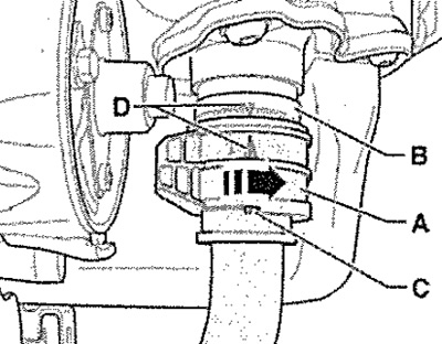
Install starter and wires. Connect connector -A- for mechatronics as follows: Arrows -D- on mechatronics -B- and connector -A-, as well as projection -C- must line up and point upwards. Then carefully connect the connector -A- up to the stop and block the shutter by turning it to the right -in the direction of the arrow-. Assemble the exhaust system in a stress-free manner and install the holder for the exhaust system on the attachment bracket. Check the adjustment of the supports! aggregates. Tighten the new gearbox bracket screws on the gearbox support bearing bracket to the specified torque, observing the tightening sequence.

Note: Additional work must be carried out when disconnecting and connecting the battery cable to earth.
Install the battery and battery bracket. Check the installation of the control lever cable, adjust if necessary. Install the air filter. Check the coolant level in the cooling system, top up if necessary. Check transmission oil level, top up if necessary. Install the left front wheel arch cover. Install the lower engine soundproofing cover. Install front wheels.
