Removing
1. Unscrew the nut securing the drive shaft to the wheel hub.
2. To turn away fastening nuts and to remove a forward wheel.
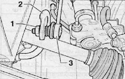
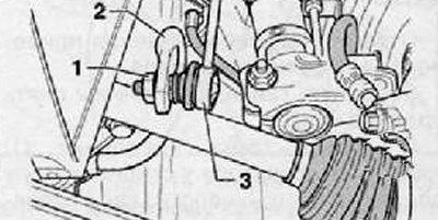
3. Loosen the fastening nut (1) stabilizer links to the anti-roll bar as shown in the figure below.
4. Pull and disconnect the rack hinge (3) from anti-roll bar (2), as shown in the figure below.
5. Remove the front wheel speed sensor.
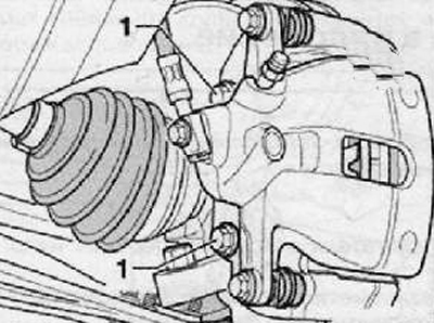
6. Unscrew the fastening bolts (1) brake caliper to the mounting bracket as shown in the figure below.
7. Disconnect and remove the brake caliper assembly with mounting bracket and hang it, using a suitable piece of wire, from the chassis parts. Do not disconnect the brake hose from the caliper. Avoid kinking and excessive bending of the brake hose.
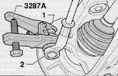
8. Unscrew the nut of fastening of the hinge of the tie rod end (1). Leave the fastening nut screwed onto the thread of the pivot pin for a few turns. Install the special puller as shown in the figure below.
9. Using a special puller, press the tie rod end pivot out of the steering knuckle eyelet (2) as shown in the picture below.
10. Unscrew finally the nut that secures the tie rod end to the steering knuckle.
11. To take the hinge of a tip of steering draft from a rotary fist.
12. Hang the tie rod from the undercarriage parts using a suitable piece of wire.
13. Remove the outer CV joint from the wheel hub. Hang the drive shaft from the undercarriage parts using a suitable piece of wire.
14. Connect the lower arm of the front suspension to the steering knuckle. Use the old nuts for this temporary fastening.
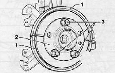
15. Unscrew the fastening screws and remove the brake disc assembly.
16. Remove the mudguard.
Note.
- Mounting tool -MP6-414 (3253) - must be installed perpendicular to the axis of the wheel hub with the wheel bearing. During removal and pressing, do not jam the wheel hub with the wheel bearing.
- The following describes 2 different possibilities for pressing out a wheel bearing with a wheel hub.
Insert the knockout tool for the side door hinge pins -3- into the space between the wheel bearing cover and the wheel hub as a contact surface for the assembly tool -2-.
Press the wheel hub with wheel bearing out of the wheel bearing housing cover.
- 1) -MP6-414/2- with -MP6-414/5-
- 2) -MP6-414/1-
- 3) -MP8-605/1-
- 4) -MP6-414/10-
- 5) -MP6-414/6-
Note.
- Instead of the tool for knocking out the pins of the side door hinges -MP8-605/1- it is also possible to use two washers (thickness approx. 25 mm, height approx. 40 mm and length approx. 220 mm), located in the space between the wheel bearing cover and the wheel hub and serving as a contact surface for the mounting tool -MP6-414 (3253) -. Location according to release tool -E-37-.
- If the release tool -E-37- from the accessory set -VAG 1459 B/2- is available, it can be used as contact surface. When doing so, ensure that the correct assembly position is maintained. The flat surfaces of the pads should point towards the wheel hub.
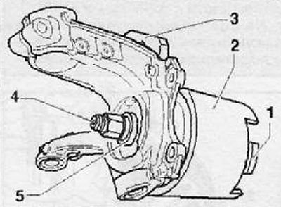
Install the release tool -3- in the space between the wheel bearing cover and the wheel hub and pre-tension it.
Press the wheel hub with wheel bearing out of the wheel bearing housing cover.
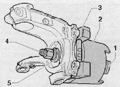
- 1) -MP6-414/2- with -MP6-414-
- 2) -MP6-414/1-
- 3) release tool -E-37- from VAG 1459 B/2
- 4) -MP6-414/10-
- 5) -MP6-414/6-
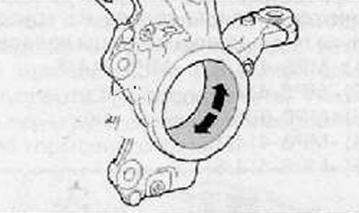
Note. Clean bore of wheel bearing cap. Lubricate the hole with Molykot grease -G 052 723 A2- over the entire area.
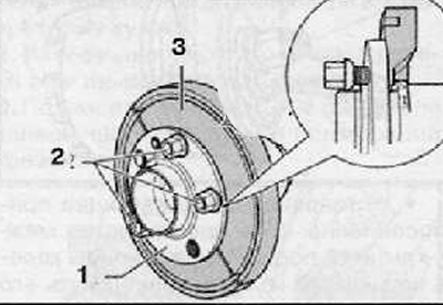
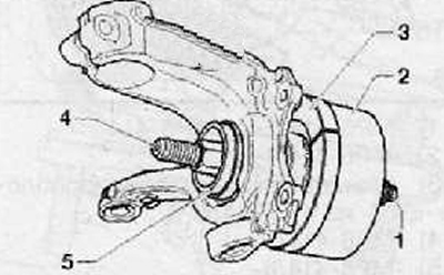
Remove grips (3) with wheel hub and with wheel bearing (1) with wheel bolts (2), as shown in the figure below.
Attention.
- The wheel bolts must not (2) protruded on the back side of the pads (3).
- The illustration below shows the installation of a wheel hub with a wheel bearing on the wheel bearing cap on a running gear with FS-III brakes.
- The selection and definition of the special tool for fitting the wheel hub with wheel bearing into the wheel bearing cap on the running gear with FS-II and C54 brakes, respectively, is the same as for the running gear with FS-III brakes.
- The wheel hub must not be wedged during pressing with the wheel bearing.
Press the wheel hub with wheel bearing into the wheel bearing cap.
- 1) -MR 6-414/5-
- 2) -T10064/1-
- 3) -T10064/6A-
- 4) -MR 6-414/10-
- 5) -T10064/4-
Press wheel hub with wheel bearing until circlip audibly engages.
Detach grips (1) from wheel hub with wheel bearing (2), as shown in the figure below.
Install the brake disc dust guard.
After installing the brake disc, fix it with a screw.
After installing the tie rod together with the tie rod end in the steering linkage arm, tighten.
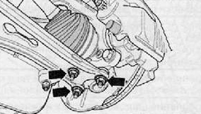
Unscrew nuts arrows (arrows), remove the lower control arm from the ball joint.
Insert the driveshaft outer joint into the wheel bearing cap.
After installing the disc wheel brake caliper in the reverse order of removal, depending on the type of disc wheel brake caliper, tighten the bolts of its fastening.
Connect the brake pad wear sensor harness connector (if the car is equipped with it).
Install the ABS wheel speed sensor.
Connect stabilizer bar (3) to anti-roll bar (2), tighten the new fastening nut (1) with the required tightening torque.
Tighten a new hex nut to secure the drive shaft.
Install the front wheel and tighten its fasteners to the required torque.
Carry out a test run.
Adjust the front wheel alignment if necessary.
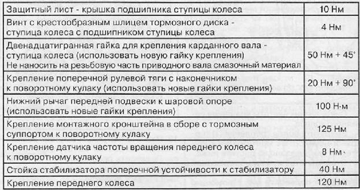
Tightening torques for threaded connections
