Removing
Note.
- The engine is removed together with the gearbox downwards.
- All cable clamps (bandages), which were loosened or cut during the removal of the engine, must be reattached in the same place when reinstalling the engine.
- Drained coolant must be drained into a clean container for disposal or subsequent use.
Attention.
- For any assembly work, especially in the engine compartment due to the narrow assembly area, observe the following rules:
- Any kind of pipeline (e.g. for fuel, hydraulic system, coolant, brake fluid, vacuum lines) and electrical wires should be laid in such a way as to restore their original condition.
- Ensure that there is sufficient space between the piping and moving or hot components to avoid damage.
1. If available, remove the anti-theft wheel bolt adapter from the trunk.
2. Remove the front wheels.
3. Disconnect the negative terminal from the battery.
4. Remove the top decorative engine cover (more, see the relevant section in this chapter).
5. Remove the air filter housing with air flow meter (G70) and air intake sleeve.
6. Remove the battery and battery holder (for details, see the relevant section in chapter Engine electrical equipment).
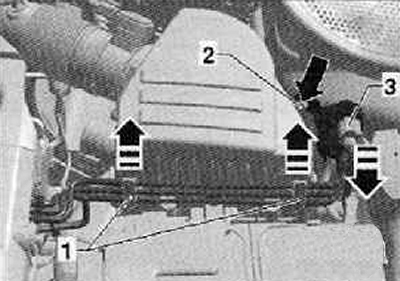
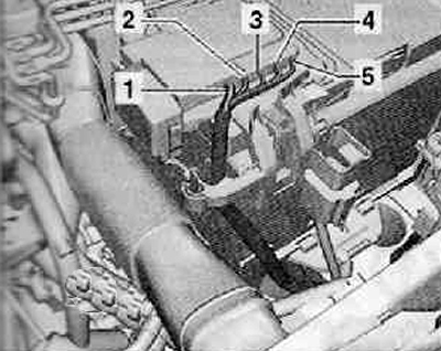
7. Disconnect the wiring harness connector (3) from the charge pressure control solenoid valve -N75- as shown in the figure below.
8. Loosen screw for boost pressure control solenoid valve -N75-, then detach and lay to one side with retainer (2), as shown in the figure below.
9. Remove the shift actuator from the gearbox (for details, see the relevant section in chapter Manual Transmission).
10. Remove the clutch release slave cylinder from the gearbox (for details, see the relevant section in chapter Manual Transmission).
Attention. After removing the slave cylinder, do not press the clutch pedal when disengaging the clutch.
11. Disconnect the vacuum hose (arrow) from the brake booster.
12. After releasing the latch, disconnect the wiring harness connector from the front of the engine control unit.
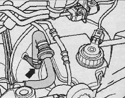
13. Disconnect the vacuum hose (arrow 1), located on the cylinder head as shown in the figure below.
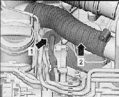
14. Disconnect the wiring harness connector (arrow), as shown in the figure below.
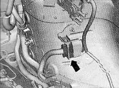
15. Carefully loosen the engine harness and wires at the attachment points (arrows), as shown in the figure below.
16. Set aside the engine wiring harness on the engine.
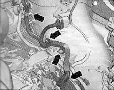
17. Disconnect the positive wire for the alternator (1), release it from its mountings and place it on the gearbox, as shown in the figure below.
18. Disconnect and release the wires from the starter and gearbox.
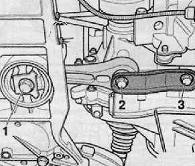
19. Unscrew the fastening bolts (1...3), remove the oscillator as shown in the figure below.
20. Remove exhaust pipe with particulate filter (for details, see the relevant section in chapter Intake and exhaust system).
21. Disconnect the fuel supply line (2) and fuel return line (1), shown in the figure below: to do this, press the release buttons and pull the fuel line.
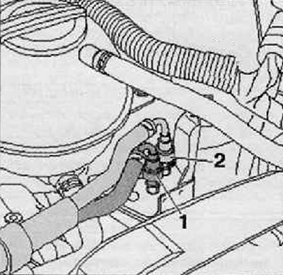
22. Loosen the stopper with your finger, pull the fuel heating valve up from the wires on the coolant surge tank, as shown in the figure below.
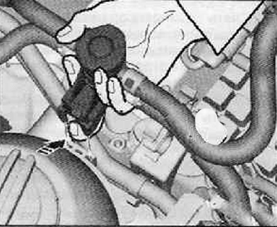
23. Press the clamps outwards, remove the fuel filter upwards.
24. Putting the fuel filter with fuel hoses aside, fix it together with the fuel heating valve on the engine.
25. Remove fuel filter holder.
26. Remove wheel arch liner (wings) right and left wheels (more. see the relevant section in chapter Body)
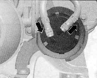
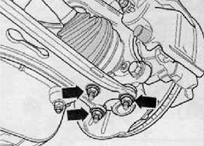
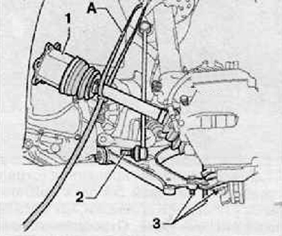
27. Loosen the fastening nuts (arrows) right ball joint to the front lower control arm, as shown in the figure below. Disconnect the front lower control arm from the ball joint.
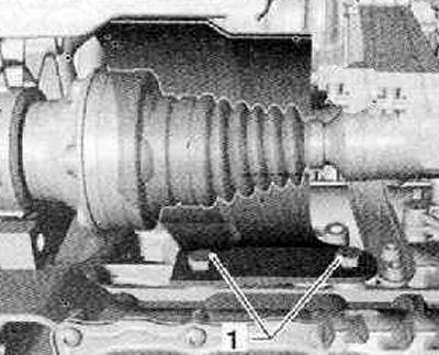
28. Unscrew the fastening bolts (1) right drive shaft guard, if fitted as shown in the figure below.
29. After removing the right drive shaft from the gearbox, hang it with a wire.
30. Remove the left drive shaft from the gearbox (for details, see the relevant section in the chapter Drive shafts).
31. Unscrew the nut securing the stabilizer bar to the stabilizer on the left side (2), as shown in the figure below. Then disconnect the rack from the anti-roll bar.
32. Unscrew the fastening nuts (3) left ball joint to front lower control arm, as shown in the figure below. Disconnect the front lower control arm from the ball joint.
33. Turn the steering knuckle assembly with the wheel hub bearing to the left until it stops.
34. Tilt the head of the ball joint of equal angular speeds outward, fix the drive shaft assembly (1) with tape (A) in the wheel arch as shown in the figure below.
35. Remove charge air hose.
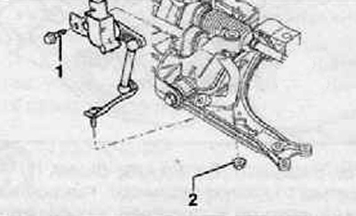
Note. With vehicle level sender installed, left front -G78-, unscrew nut (2) from the lower arm of the front suspension on the left side, as shown in the figure below.
36. Unscrew the fastening screws (arrows), shown in the figure below.
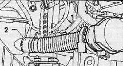
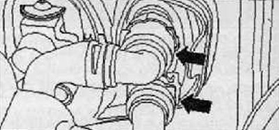
37. Loosen the hose clamp (2), shown in the figure below.
38.Disconnecting the wiring harness connector (1) on the charge pressure sender -G31- with the intake air temperature sender -G42-, remove the charge air connection to the right as shown in the figure below.
39. Drain the coolant.
40. Disconnect the remaining coolant hoses from the radiator.
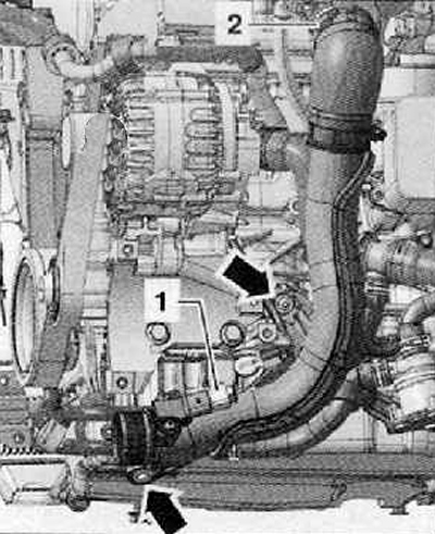
41. Disconnect wire wire «masses» (1) from the unit foot as shown in the figure below.
42. Disconnect the expansion tank of the cooling system from the bracket, then put it on the engine.
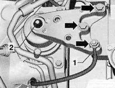
43. Having disconnected the filler neck of the windshield washer reservoir (1), place it aside as shown in the figure below.
For vehicles with air conditioning
44. Remove alternator (for details, see the relevant section in chapter Engine electrical equipment).
Attention.
- Risk of injury from coolant.
- The refrigerant circuit of the air conditioner must not be opened.
Attention.
- Risk of damage to the condenser and coolant lines and hoses.
- Coolant lines and hoses must not be overstretched or bent at sharp angles.
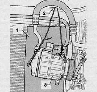
45. Remove A/C compressor from accessory bracket (see the relevant section in chapter Heating, ventilation and air conditioning system).
46. Fix the air conditioning compressor (3), for example, for a complete body front wall module as shown in the figure below. Cardboard should be fixed to the radiator wall as protection (1).
Continuation for all cars
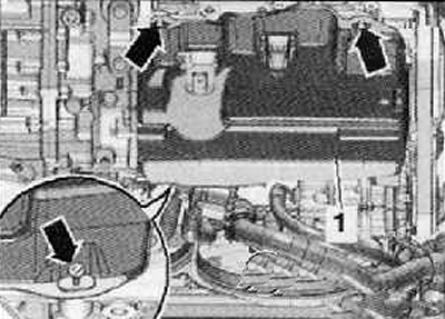
47. Remove soundproofing (1) oil pan, for which loosen the fasteners (arrows), as shown in the figure below.
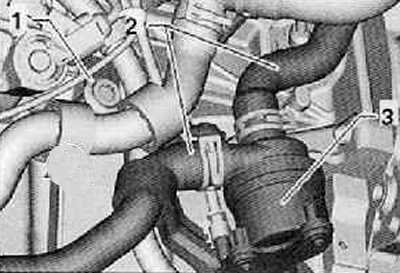
48. Remove the screw (1), disconnect coolant pump 2 -V178- (3) and set it aside as shown in the picture below.
49. Disconnect other required plug-in connectors on the engine and gearbox, or also disconnect the wires leading to the engine and gearbox.
50. Remove quick couplers (arrows) on the radiator of the heating system (heat exchanger), as shown in the figure below.
51. Disconnect all remaining connecting hoses, coolant hoses, intake hoses and air intake hoses from the engine.
52. Having disconnected all remaining plug connectors on the engine and gearbox, put the corresponding electrical wires aside.
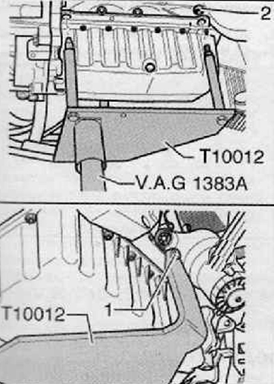
53. Connect engine mount bracket (Т10012) with a nut (2) and screw (1) to the cylinder block, tighten with a tightening torque of 20 Nm as shown in the figure below.
54. Inserting a device for removing and installing the engine and gearbox (VAG 1383 A) into the engine support bracket, lift slightly.
Note. Use a ladder to unscrew the engine and gearbox mounting bolts.
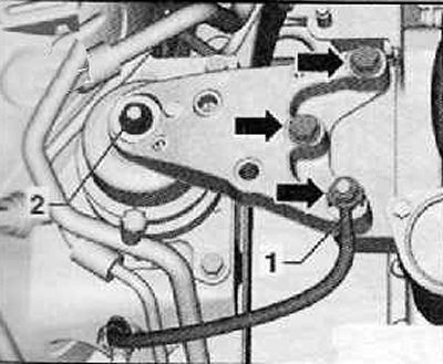
55. Remove the mounting bolts connecting the engine mount and the engine mount bracket (arrows), as shown in the figure below.
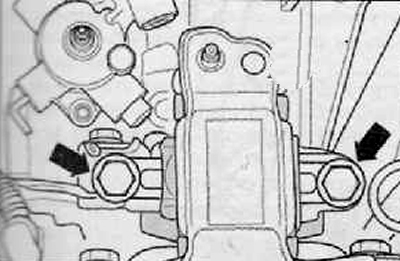
56. Remove the assembly support on the gearbox. Loosen the fixing screws (arrows), shown in the figure below.
Note.
- Check that all hose and wire connections between the engine, gearbox and body are disconnected.
- While lowering, drive the engine with gearbox in such a way as to prevent damage.
- By moving the support beam along the axis, you must provide the necessary space for lowering the unit.
57. Carefully lower the engine with gearbox. In this case, as necessary, the engine with the gearbox should be turned or moved.
58. Remove gearbox from engine.
Installation
Note.
- Observe all safety measures and instructions for assembly work on the supply and injection system, on the charge air system.
- When installing, replace the self-locking nuts and screws with an additional twist.
- Replace O-rings and seals.
- All cable clamps must be fixed in the same place during assembly.
- All hose connections must be secured with appropriate tube clamps.
Attention.
- For any assembly work, especially in the engine compartment due to the narrow assembly area, observe the following rules:
- Any kind of pipeline (e.g. for fuel, hydraulic system, coolant, brake fluid, vacuum lines) and electrical wires should be laid in such a way as to restore their original condition.
- Ensure that there is sufficient space between the piping and moving or hot components to avoid damage.
Note.
- Clean the splines of the input shaft and, on the already used multi-plate clutch, clean the splines of the hub, remove rust and apply a very thin layer of grease -G 000 100- to the splines. Then shift the disk on the shaft back and forth, thereby ensuring its free play in the splines of the shaft. Always remove excess grease.
- After installing the clutch, check that the clutch disc is correctly centered.
- Check the clutch release bearing for wear. A worn clutch release bearing should be replaced.
1. Check the use of centering sleeves in the cylinder block for centering the engine and gearbox and, if necessary, apply them.
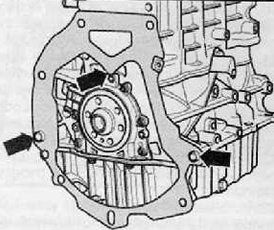
2. Ensure that the intermediate plate is hung from the flange seal and pushed onto the dowel sleeves (arrows), as shown in the figure below.
3. Connect the gearbox to the engine, install and tighten the gearbox mounting bolts to the required tightening torque (for details, see the relevant section in chapter Manual Transmission).
4. Install the engine assembly with the gearbox in the engine compartment.
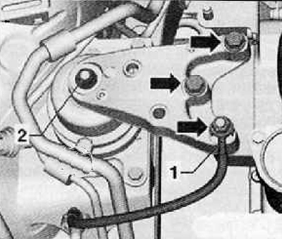
5. Tighten the engine mount assembly bolts (arrows), as shown in the figure below.
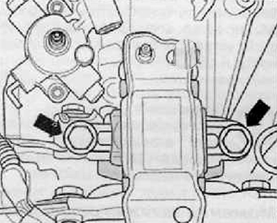
6. Manually screw in gradually the bolts of the gearbox support (arrows), as shown in the figure below.
7. Remove engine support bracket (Т10012).
8. Install the front part of the exhaust pipe with the particulate filter (for details, see the relevant section in chapter Intake and exhaust system).
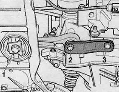
9. Install the oscillating bearing, then install and tighten the new bearing-to-gearbox bolts (2) And (3) and to the front suspension subframe (1), as shown in the figure below.
10. Install the left and right drive shafts (for details, see the relevant section in chapter Drive shafts).
11. Install the slave cylinder of the clutch release actuator and, if necessary, remove air from the clutch system (for details, see the relevant section in chapter Manual Transmission).
12. Install the gearshift drive to the gearbox and adjust.
13. Install the A/C compressor to the accessory bracket (for details, see the relevant section in chapter Heating system. ventilation and air conditioning).
14. Install alternator (for more details, see the relevant section in chapter Engine electrical equipment).
15. Install the V-ribbed implement drive belt.
16. All hoses should be connected to the engine.
17. After connecting the electrical connectors, fix the electrical wiring.
18. Carry out work related to connecting the battery.
19. Fill in coolant.
20. Check oil level.
21. Install the wheel arch liner of the left and right wheels (for details, see the relevant section in chapter Body).
22. Install the lower engine cover.
23. Fill the system and remove air from the supply system. To do this, connect the diagnostic, measuring and information system (VAS 505x) and execute the function "Removing air from the power system". The fuel pump is only active for 180 seconds at this time.
24. Check the tightness of the power system.
25. Carry out a test run.
26. Count all fault memories, eliminate possible faults and reset the contents of the fault memory.
Note. After resetting the contents of the fault memory of the engine control unit, a new readiness code must be generated.
