2. Remove camshafts (see relevant section in this chapter).
3. For proper installation, the attachment of the rocker arms to the hydraulic tappets should be marked.
4. Remove the rocker arms together with the hydraulic pushers, set them aside on a clean surface
5. Set the piston of the corresponding cylinder to BDC.
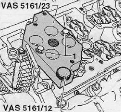
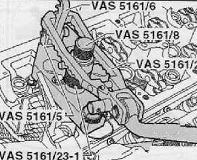
6. Install guide plate (VAS 5161/23) on the cylinder head. as shown in the picture below.
7. Hand screw the guide plate on the side of the intake manifold with a knurled bolt (VAS 5161/12) and on studs - with two Mb nuts without shoulder (1) so that she fits.
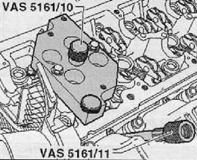
8. Screw the sealing bolts into the guide plate (VAS 5161/10).
9. Screw the adapter by hand (VAS 5161/11) into the corresponding thread of the glow plug.
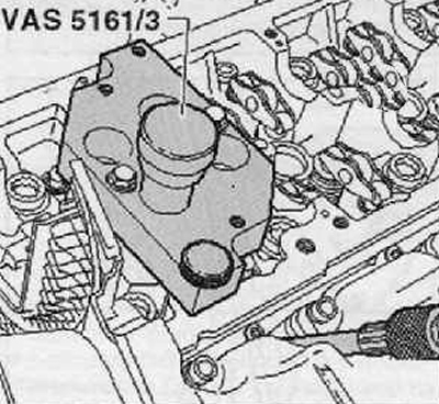
10. Insert a mandrel into the guide plate (VAS 5161/3) and with a plastic hammer, the jammed valve cotters should be released.
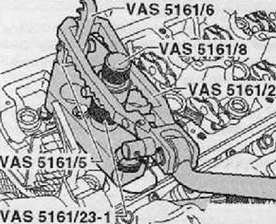
11. Screw the part with stops into the guide plate (VAS 5161/6) with suspension fork (VAS 5161/5).
12. Install knurled spacer ring (VAS 5161/23) (1) on the assembly pin (VAS 5161/8).
13. Connect the adapter with a standard spacer to a compressed air source and apply constant pressure to it. Minimum pressure: 0.6 MPa (6 bar) excess pressure.
14. Hanging the pressure fork (VAS 5161/2) on the guide piece with stops, press the assembly pin down.
15. At the same time, turn the knurled screw of the assembly pin to the right so that the tips enter the valve cotters.
16. Turn the knurled screw left and right, as a result of which the valve cotters will be pressed apart and enter the assembly pin.
17. Release the pressure fork.
18. Remove the assembly pin with the knurled spacer.
19. Remove valve spring with valve spring plate.
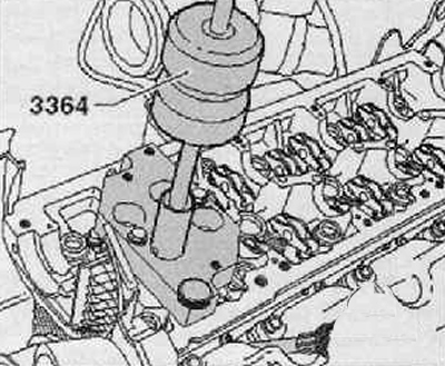
20. Remove the valve stem oil seal using a valve o-ring remover (3364).
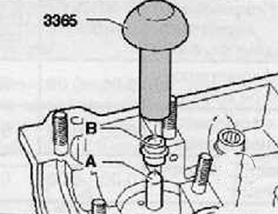
21. Put a plastic sleeve on the valve stem (A), which comes complete with new valve stem seals (IN), as shown in the figure below.
22. Lightly oil the sealing lip of the new valve stem seal.
23. Install the valve stem cap on the plastic sleeve.
24. Carefully press the valve stem seal onto the valve guide using a valve seal driver (3365).
25. Remove the protective plastic cap.
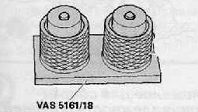
26. If the valve cotters were removed from the assembly pin, then they must first be inserted into the fixture (VAS 5161/18). The large diameter of the valve cotters points upwards.
27. To put on a valve spring and a valve spring plate.
28. Pressing the assembly pin on top of the tool for extracting and installing valve cotters, grab the valve cotters.
29. Install the trunnion back into the guide plate (VAS 5161/23).
30. Pressing the pressure fork down, turn the knurled screw to the left and pull it upwards, as a result of which the valve cotters will sit firmly.
31. Remove the load from the pressure fork while still pulling the thumb screw.
32. Repeat all the above operations with the remaining valves.
33. Installation is carried out in the reverse order of removal.
Follow that. that all rocker arms are correctly seated at the ends of the valve stems and that they are properly secured to their respective hydraulic tappets.
Install camshafts (see the relevant section in this chapter).
Install glow plugs.
