Removing
1. Remove the air filter housing assembly with the mass air flow sensor.
2. Remove the battery and its support pad (for details, see the relevant section in chapter Engine electrical equipment).
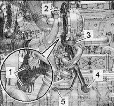
3. Disconnect the wiring harness connector (1) from the boost pressure regulator position sensor on the turbocharger, as shown in the figure below.
4. Disconnect the vacuum hose (2) from the turbocharger assembly as shown in the figure below.
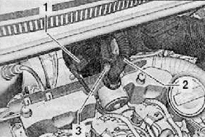
5. Remove the crankcase ventilation hose (1), by pressing the unlock buttons as shown in the figure below.
6. Release the intake hose leading to the air intake sleeve.
7. Unscrew the fastening screw (3), fold air intake sleeve with intake manifold back and disconnect from turbocharger.
8. Remove the air intake sleeve.

9. Unscrew the fastening screw (1) from the charge air pipe, loosen the clamp (2), as shown in the figure below.
10. Unscrew the fastening screw (arrow) on the charge air pipe as shown in the figure below.
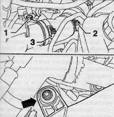
11. Unscrew the fastening screws (arrows), remove the connecting hose as far as possible from the pulsation damper, as shown in the figure below.
12. Press the charge air pipe to the left, as far as possible to the left.
13. Remove the pulsation damper.
Attention.
- The exhaust gas temperature sender 1 -C235- closes off the upper screw connection of the turbocharger support.
- The exhaust gas temperature sender 1 -G235- must not be bent. For this reason, it must be removed.
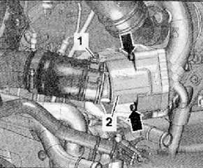
14. Remove exhaust gas temperature sender 1 -G235- (1), shown in the figure below.
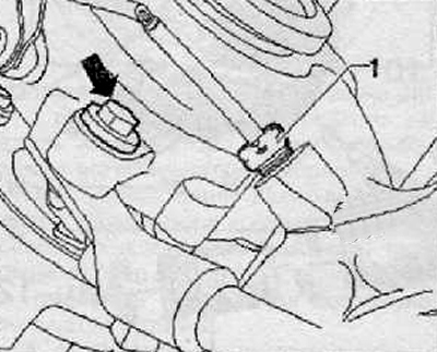
15. Loosen the union nut (2), shown in the figure below. While doing this, hold the hexagon of the connecting pipe with a suitable 14 mm wrench.
16. Unscrew the fastening screws (1) And (3) and bolts with holes (4, 5), then remove the turbocharger support with oil supply pipe as shown in the figure below.
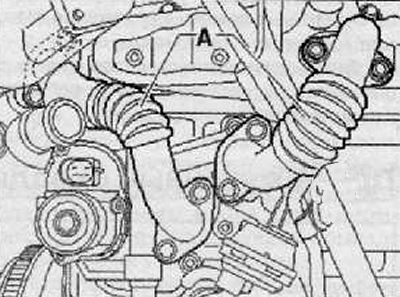
17. Remove connecting tubes (A), leading to the EGR cooler.
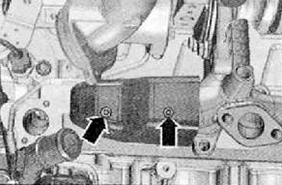
18. To remove a thermoinsulating covering to the left on a final collector.
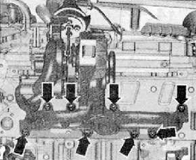
19. Unscrew the fastening nuts (arrows), then remove the turbocharger with exhaust manifold from the cylinder head as shown in the figure below.
Installation
1. Installation is carried out in the reverse order of removal Observe. the conditions below
Attention. Before proceeding with the installation, it must be checked that the connecting element of the lubrication return line is not bent and thus overtightened. If this is not the case, then microcracks may have formed here, the consequences of which are leaks. If necessary, the oil drain line must be replaced before proceeding with the installation of the turbocharger.
Note.
- Replace seals, O-rings and self-locking nuts.
- Fill the turbocharger with engine oil through the lubrication line connection.
- The charge air pipes and hoses, as well as their connections, must not be exposed to oil or grease before installation.
- All hose connections must be secured with spring hose clamps.
Check oil level.
Note. After installing the turbocharger, leave the engine running for approximately 1 minute at idle to allow oil to circulate through the turbocharger.
