Note.
- Necessary special devices, control and measuring devices, as well as auxiliary means:
- Adapter (adapter) for dial gauge -T10170-.
- Camshaft positioner -T10171- or -T10171A-.
- Dial indicator.
1. Remove the cylinder head cover and air filter.
2. Remove the camshaft covers.
3. Remove the ignition coil of the 1st cylinder.
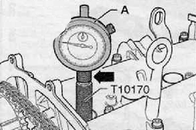
4. Screw adapter for dial gauge -T10170- into the spark plug thread as far as it will go.
5. Set deviation indicator (A) with extension T10170/1 - up to the stop, tighten it with a clamping nut (arrow), as shown in the figure below.
6. Turn the crankshaft in the direction of rotation of the engine shaft until the piston of the 1st cylinder is at TDC. Mark the position on the deviation indicator with a small arrow.

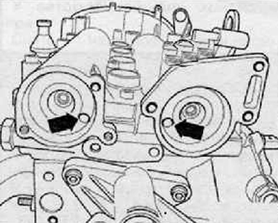
7. Holes (arrows) in the camshafts must be in the position shown in the figure. Turn the crankshaft one turn if necessary (360°).
Note.
- If the crankshaft turns more than 0.01 mm behind TDC, then turn the crankshaft back by about 45. Then turn it in the direction of rotation of the engine shaft to the TDC position of the 1st cylinder.
- Permissible deviation from TDC of the piston of the 1st cylinder:±0.01 mm.

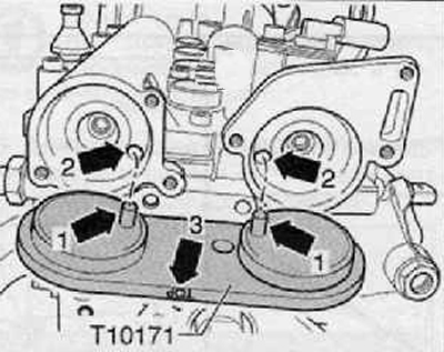
8. Insert camshaft locking tool -T10171- or -T10171A- into the holes in the camshafts as far as it will go. Stop mandrels (arrows 1) should go into the holes (arrows 2), as shown in the figure below. Need an inscription "TOR" (arrow 3) could be read from above.
- If it is not possible to insert the camshaft locking tool -T10171- or -T10171A- into the camshaft bores as far as it will go, the valve timing has not been adjusted and must be readjusted.
- The valve timing is set if it is possible to fit the camshaft locking tool -T10171- or -T10171A- into the camshaft bores as far as it will go.
9. Further installation is carried out in the reverse order of removal.
- Replace the O-rings of the camshaft covers and lubricate them with oil before proceeding with installation.

