Note. Necessary special control devices and measuring devices, as well as auxiliary means:
- Pliers for hose clamps.
- Sealing agent -D 176 501 A1-.
- Screw М6х70 (2 pcs.): Modify the screws by cutting off the screw heads.
- Gasket Stripper Seal Remover (storage code GST item no. R 34402), manufacturer Retech s.r.o.
- Cleaning and degreasing agent, e.g. -D 000 401 04-.
- Protective gloves and goggles.
Removing
1. Drain the coolant into a prepared container.
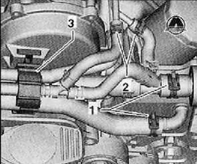
2. Releasing the clamps (1) And (2), disconnect the coolant hoses as shown in the figure below.
3. Release the fastening clamp (3). pull it out with the coolant hoses upwards, as shown in the figure below.
4. Coolant hoses should be laid back.
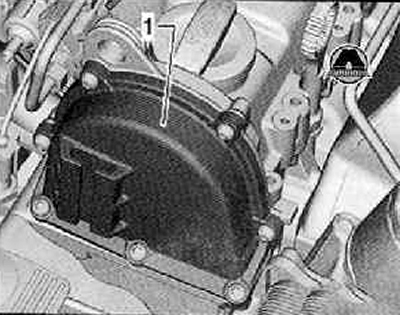
5. Remove all mounting screws from the upper timing chain case (1), as shown in the figure below.
6. Carefully remove the upper timing chain cover.
Installation
1. Installation is carried out in the reverse order of operations, and the following instructions must be observed.
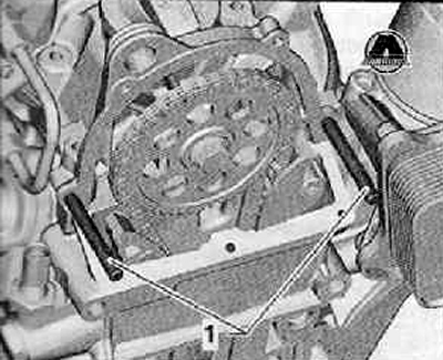
To facilitate the installation of the timing gear housing cover, screw in two M6x70 studs (1) into the cylinder head cover.
Attention. Protective gloves and goggles should be used when working with seal remover and degreaser.
2. Remove sealant residue from the sealing surfaces on the timing gear top cover and on the cylinder block with a chemical seal remover.
3. Degrease the sealing surfaces.
4. Cut off the tip of the tube jet at the front mark with scissors (∅ jet - approx. 3 mm).
Note.
- Installation must not last longer than 6 minutes from the moment the sealing agent is applied to the tightening of the fixing screws with a torque of 8 Nm.
- The sealant begins to harden after 6 minutes.
- Remember that the fixing bolts are tightened in two steps.
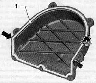
5. Apply special sealant (D 176 501 A1) on the sealing surface (1), shown in the figure below.
6. In the area shown in the figure below (arrow) slightly more sealant should be applied.
7. Install the upper timing chain cover (1) on guide pins (2), as shown in the figure below.
8. To move a cover on guides against the stop in a head of the block of cylinders. Make sure the cover is not skewed.
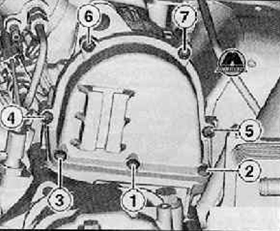
9. Unscrew the guide bolts from the holes in the cylinder head. Install the upper timing cover bolts and tighten them to the required torque in the sequence shown below.
First approach. Tighten the mounting bolts in the sequence shown below with a tightening torque of 5 Nm.
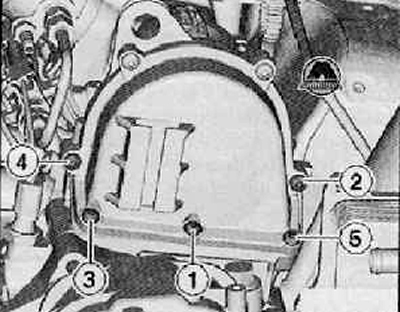
Second approach. Tighten the timing chain cover bolts in the sequence shown in the figure below to a torque of 8 Nm.
10. Move the clamp (3), to fully install it into the mounting bracket, as shown in the figure below.
11. Connect the hoses of the cooling system to the nozzles, then tighten the hose clamps (1) And (2), as shown in the figure below.
12. Fill the cooling system with coolant.

