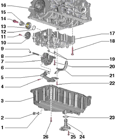
41.1 Installation details of the oil pan, oil pump and balancer shaft module
1 O-ring, cannot be separated from the plug 2
2 Drain plug, to be replaced together with ring 1, 30 Nm
3 Oil pan, installed on silicone sealant D176 404A2
4, 20, 22 Bolt, 9 Nm
5 Suction tube
6, 23 O-ring, to be replaced
7 Oil pump with 4.5 bar control valve and 10 bar relief valve
8 Oil pump drive shaft
9 Retaining ring in groove
10 Balance shaft helical gear
11 Bolt, to be replaced, 20 Nm, then retighten 90°
12 Gear support washer 13, to be replaced
13 Intermediate gear for balancing shaft drive, to be replaced
14 Bolt with washer, to be replaced, 90 Nm, then retighten by 90°
15 Gear hub 13, to be replaced
16 Helical crankshaft gear
17 Balance shaft module
18 Bolt, to be replaced 13 Nm (M7) or 20 Nm (M8), then tighten to 90°
19 Centering sleeves
21 Suction tube
24 Sensor "G266" engine oil level and temperature
25 Self-locking bolt, replaceable, 9 Nm
26 Bolt, 15 Nm
2. Details of installation of the oil filter housing and oil cooler are indicated on Ref. illustrations.
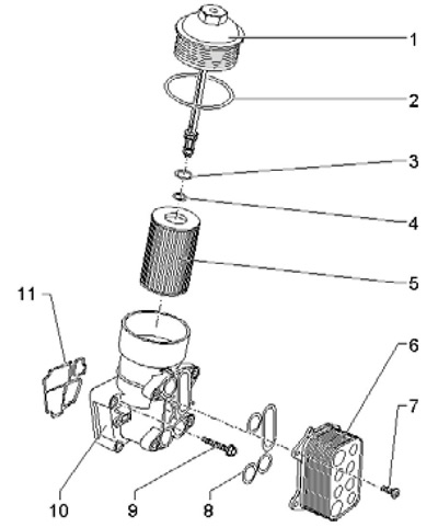
41.2 Installation details of the oil filter housing and oil cooler
1 Cap with hexagon 32 mm, 25 Nm
2-4 O-ring, to be replaced
5 Filter element
6 Oil cooler
7 Bolt, 5 Nm, then 11 Nm
8 Gasket, to be replaced
9 Bolt, to be replaced, 14 Nm, then retighten 90°
10 Filter element and oil cooler holder
11 Gasket, to be replaced
3. A description of the removal / installation of parts of the lubrication system is not given due to the simplicity of these procedures.
Removal and installation of the balancer shaft module
4. Remove the crankshaft pulley.
5. Turn the crankshaft to the TDC position and block the crankshaft gear by installing tool T10050 between the teeth on the front side (see illustration 36.13). Tags (2) on the gear wheel and on the T10050 fixture (1) must be aligned when the fixture pin enters the hole in the sealing flange.
6. Remove the engine oil pan.
7. Turn out bolts in sequence (8-1 on resist. illustrations) and remove the balance shaft module along with the oil pump.
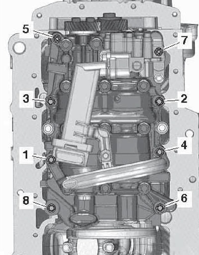
41.7 Tightening sequence of the balance shaft module mounting bolts (8 bolt version)
Installing the old balancer shaft module
Note: If the idler gear bolt has been loosened, the crankshaft gear or the entire crankshaft has been replaced, a new idler gear must be installed and the hub replaced (including bolt) and support washers. Otherwise, the backlash of the teeth will be disturbed.
8. The following procedure assumes that the drive gear on the crankshaft has not been replaced, the crankshaft has not been removed, and the intermediate gear has not been loosened. The crankshaft must be locked at TDC with tool T10050.
9. Block the balance shaft with tool T10255, turning the shaft if necessary (see resist. illustration). The pin of tool T10255 must fit into the groove in the shaft.
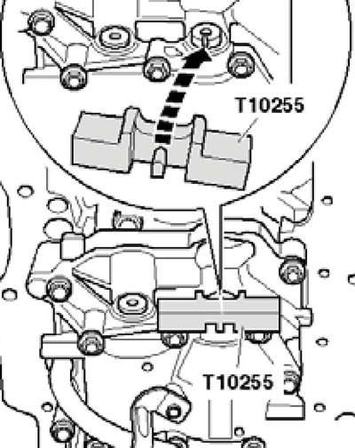
41.9 Balance shaft lock
10. Make sure that both centering sleeves for the balancer shaft module are in place in the cylinder block.
11. Position the locked balancer shaft module on the cylinder block so that the idle gear meshes with the crankshaft drive gear. The intermediate gear should also have a little backlash.
12. Tighten the bolts (see illustration 41.7) fastening the balance shaft module as follows:
- bolts (1-8) - by hand;
- bolts (1-8) - with a force of 6 Nm;
- bolts (5 and 7) - with a force of 13 Nm;
- bolts (1-4, 6 and 8) - with a force of 20 Nm;
- bolts (1-8) - tighten at an angle of 90°.
13. Remove the tools for blocking the balance shafts (Т10255) and crankshaft (Т10050).
14. Further installation is carried out in the reverse order of removal.
Installing a new balancer shaft module
Note: The helical gear of the balance shaft module must be installed with the correct backlash (0.038-0.072), for which a coating is applied to the new intermediate gear. The coating is quickly erased and provides the necessary backlash. For these reasons, a new balancer shaft module must always be installed with a new counter gear.
15. Make sure the crankshaft is locked with tool T10050.
16. Before positioning the balance shaft module on the cylinder block, loosen the bolt (1 per resist. illustrations) new idler gear at an angle of approximately 45°. Make sure both centering sleeves for the balance shaft module are in place and place the module on the cylinder block.
Note: Be careful not to damage the coating on the intermediate gear.
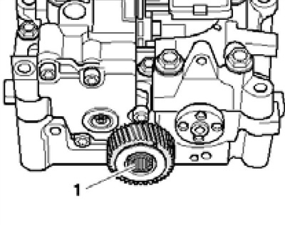
41.16 Idle gear bolt
17. Tighten the balance shaft module mounting bolts as described in paragraph 12.
18. Block the balance shaft with tool T10255, turning the shaft if necessary (see illustration 41.9). The pin of tool T10255 must fit into the groove in the shaft.
19. Gently put its gear on the balancer shaft, while slightly pressing the intermediate gear to the side. Make sure the threaded holes in the balancer shaft line up with the oblong holes in its gear. If the slotted holes in the gear cannot align with the threaded holes in the shaft, the balance shaft gear should be installed rotated further by a certain number of teeth. Tighten the gear firmly (see resist. illustration) and remove tool T10255.
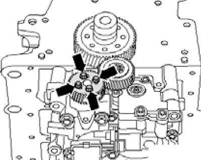
41.19 Balancing shaft gear bolts
20. Invite an assistant and perform the described steps at the same time. Push into intermediate gear (3 on resist. illustrations) block of wood and firmly press it in the direction of the arrow into the teeth of the drive gear (2) and gears (1) balance shaft. At the same time, rotate the gear slightly (1) counterclock-wise.
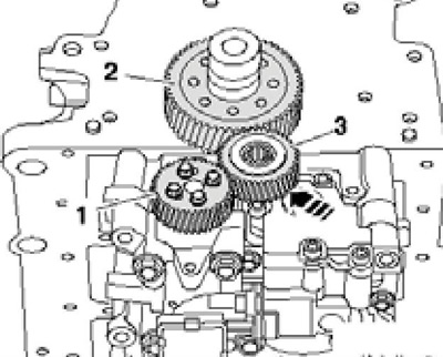
41.20 Installing the intermediate gear
Tighten the intermediate gear bolt firmly.
21. Remove tool (Т10050) to lock the crankshaft. After that, the backlash should not be felt with light pressure by hand.
22. Further installation is carried out in the reverse order of removal.
Replacing the crankshaft gear
23. Remove the front sealing flange (see Section 37).
24. Remove the balance shaft module (see relevant subsection above).
25. Insert support T10392 / 1 into the end of the crankshaft (see resist. illustration).
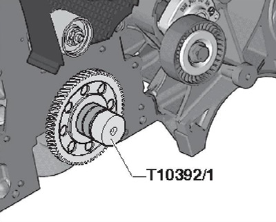
41.25 Support Т10392/1
26. Install the T10392 puller in the holes of the gear (see resist. illustration) and turn it clockwise, then screw in the centering pins (A).
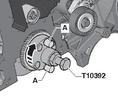
41.26 Puller Т10392
27. Holding the crankshaft with a wrench (And on the opposite illustrations), remove the gear from the crankshaft by screwing the spindle with a wrench (IN).
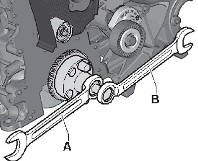
41.27 Removing the crankshaft gear
28. Make sure the end of the crankshaft is clean.
29. Lay a new gear on the electric stove with the marking up, heat the gear to a temperature of 200-240°C, grab it with swedes or tongs and quickly install it on the crankshaft without distortion until it stops using tool No. 10-203 (see resist. illustration).

41.29 Installing the crankshaft gear
Note: When holding the gear, do not damage its teeth. If the gear is heated to 200°C, there is only 4 seconds to set; with more heating, there is more time: for example, at 220°C, the gear can be installed within 6 seconds. To monitor the gear temperature, use a suitable thermometer or multimeter in combination with a temperature probe. Wear heat protective gloves.
30. Let the gear cool for a few minutes and install the balance shaft module.
