Petrol models
The fuel system consists of: a rear-mounted fuel tank with a filler neck, a fuel supply module with a fuel gauge, a fuel gauge No. 2 with a jet pump, a carbon vapor absorber, fuel lines, a fuel filter, and a fuel injection system, controlled by an electronic engine control unit (ECM). The composition of the fuel injection system includes: injection pump, fuel distribution line and injectors.
A fuel supply module is installed in the fuel tank, which is an assembly of a fuel reserve sensor and a fuel pump with a strainer. The fuel reserve sensor is designed to display the fuel reserve on the instrument cluster. The electric fuel pump is designed to create pressure in the low-pressure part of the fuel supply system. On/off and performance of this pump (depending on the crankshaft speed and engine operating mode) through the PWM signal is controlled by the corresponding control module "J538", working on the basis of information from the ECM. The mesh fuel filter is designed for the life of the vehicle and does not need to be replaced.
The jet pump is designed to transfer fuel to the fuel supply module from another part of the tank. The #2 fuel gauge integrated with the jet pump is designed to provide more accurate fuel gauge information.
In the event of an accident, the fuel cut-off function may be activated to reduce the risk of ignition of leaked fuel. This function disables the fuel pump at the level of its relay.
To improve engine starting performance, the fuel pump relay is energized for two seconds when the driver's door is opened to pre-pressurize the fuel system. Therefore, for safety during repairs without disconnecting the battery, disconnect the connector of the fuel pump control unit.
The fuel tank is vented using vent valves that vent fuel vapors to the EVAP canister (see Part B).
High pressure fuel pump is designed to create high fuel pressure to implement the principle of direct fuel injection (FSI). The injection pump is driven through a pusher: on a 3.6 liter engine, the pusher is driven by a 2-cam eccentric with a gear from the timing chain, and on other engines the pusher is driven by a separate camshaft cam.
The fuel from the injection pump is accumulated in the fuel distribution line, which equalizes its pressure, and then injected directly into the combustion chambers through the injectors. The moment and duration of fuel injection are determined by the ECM using signals from various sensors (see section 2).
The location of the components of the power system are shown in illustrations 1.1ag.
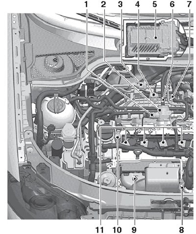
1.1a Location of the components of the power supply system on the right side of the engine compartment of 1.4 l models
1 valve "N276" fuel pressure adjustment
2 injection pump with valve 1
3 Solenoid valve No. 1 "N80" adsorber purge
4 MAP sensor "G71" with IAT sensor "G42"
5 ECM "J623"
6 Knock sensor #1 "G61", rear on the cylinder block, 20 Nm
7 SKR sensor "G28"
8 Lambda probe "G39" with heating element "Z19"
9 Post-catalytic lambda probe "G130" with heating element "Z29"
10 Valve #1 "N205" Timing timing adjustment
11 Ignition coils
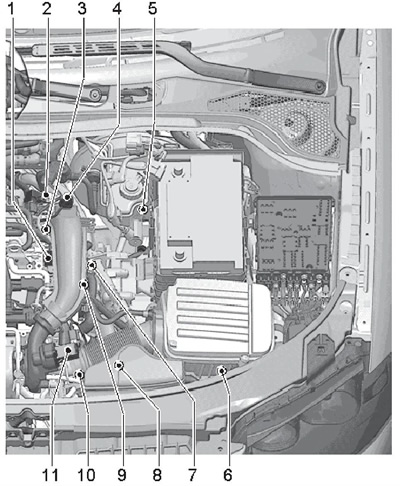
1.1b Location of the components of the power supply system on the left side of the engine compartment of 1.4 l models
1 CMP sensor "G40"
2 Throttle valve module "J338"
3 Sensor "G247" fuel pressure
4 Sensor "G31" boost pressure with IAT sensor No. 2 "G299"
5 Clutch position sensor "G476"
6 Sensor "G83" coolant temperature at the radiator outlet
7 ECT sensor "G62"
8 Electrical wiring connectors for lambda probes
9 D/V "F1" engine oil pressure, in the cylinder head
10 Solenoid valve "N75" boost pressure adjustment, screwed into the turbocharger
11 Valve "N249" air recirculation turbocharger
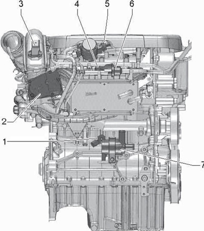
1.1c The location of the components of the power system on the intake side of the engine 1.4 l
1 Knock sensor #1 "G61", rear on the cylinder block, 1 20 Nm
2 Throttle valve module "J338"
3 Sensor "G31" boost pressure with IAT sensor No. 2 "G299"
4 MAP sensor "G71" with IAT sensor "G42"
5 Valve "N276" fuel pressure adjustment
6 Solenoid valve No. 1 "N80" adsorber purge
7 Coolant circulation pump "V50"
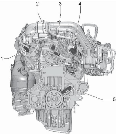
1.1d Location of the components of the 1.4 l engine power supply system on the side of the manual transmission
1 Solenoid valve "N75" boost pressure adjustment, screwed into the turbocharger
2 D/V "F1" engine oil pressure, in the cylinder head
3 ECT sensor "G62"
4 Sensor "G247" fuel pressure
5 SKR sensor "G28"
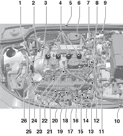
1.1e Location of the components of the power supply system in the engine compartment of the 1.8 and 2.0 l models
1 Solenoid valve No. 1 "N205" camshaft phase adjustment
2 Solenoid valve "N75" boost pressure adjustment, screwed into the turbocharger
3 valve "N249" turbocharger vent screwed into the turbocharger
4 ignition coils
5 ECM "J623"
6 Pre-catalytic lambda probe "G39" injection pump
7 Solenoid valve "N276" fuel pressure regulator, is part of
8 injection pump
9 Connector lambda probe 6, in the bracket on the bulkhead
10 Sensor "G83" coolant temperature at the radiator outlet
11 Setting piece for intake manifold flap valve
12 Valve "N316" intake manifold flaps
13 SKR sensor "G28", on the front side of the cylinder block, bottom left
14 Sensor "G31" boost pressure, screwed into the pressure air tube for module 18
15 Knock sensor connector No. 1 "G61", under intake manifold
16 CMP sensor connector "G40", under intake manifold
17 8-pin connector for injectors, under intake manifold
18 Throttle valve module "J338"
19 Solenoid valve No. 1 "N80" EVAP canister purge
20 Sensor "G42" IAT
21 Knock sensor No. 1 "G61", screwed into the cylinder block under the intake manifold, 20 Nm
22 ECT sensor "G62", in the coolant pump housing
23 CMP sensor "G40", screwed into the cylinder head cover from the front
24 Sensor "G247" fuel pressure, in the fuel distribution line
25 Sensor "G336" intake manifold flap position
26 Sensor "F22" engine oil pressure (see chapter 2)
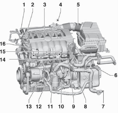
1.1f The location of the components of the power system on the engine 3.6 l, part 1
1 Solenoid valve No. 1 "N80" EVAP canister purge
2 Sensor "G410" low fuel pressure
3 ignition coils
4 ECM "J623"
5 Sensor "G70" mass air flow
6 Block connector "Mechatronic" DSG
7 Sensor "G83" coolant temperature at the radiator outlet
8 Valve "N276" fuel pressure adjustment, in injection pump
9 Sensor "G247" fuel pressure, in the fuel distribution line of cylinders No. 2, 4, 6
10 SKR sensor "G28"
11 Knock sensor #2 "G66", between cylinders 4 and 6
12 Sensor "F1" engine oil pressure (see chapter 2)
13 Coolant circulation pump "V55"
14 Injectors of cylinders №№2,4,6
15 Injectors of cylinders №№1,3,5
16 Knock sensor #1 "G61", between cylinders 1 and 3
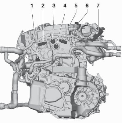
1.1g The location of the components of the power system on the engine 3.6 l, part 2
1 Sensor "G83" coolant temperature at the radiator outlet
2 CMP sensor "G40", for intake camshaft
3 Solenoid valve No. 1 "N205" Timing timing adjustment (inlet)
4 Solenoid valve No. 1 "N318" Timing timing adjustment (release)
5 CMP sensor No. 2 "G163", for exhaust camshaft
6 Resistor "N79" PCV heating
7 Module "J338" throttle valve
Diesel models
The fuel delivery system includes: a rear-mounted fuel tank with a filler neck, a fuel delivery module, fuel lines, a fuel cooler, a fuel filter, an additional fuel pump, as well as an electronic distributed sequential fuel injection system controlled by an electronic engine control unit (ECM). The composition of the distributed sequential fuel injection system on models "TDI-CR" includes: high pressure fuel pump (injection pump), fuel distribution line "Common Rail", piezo injectors, fuel pressure pipes and fuel return lines. The composition of the distributed sequential fuel injection system on models "TDI-PD" includes: fuel pump (combined with a vacuum pump into a single "tandem" pump), supply and return lines in the cylinder head and pump injectors.
The location of the components of the power system are shown in illustrations 1.2a-b. The scheme of the fuel supply system is shown in illustration 1.3. Further description is for models with fuel rail "TDI-CR".
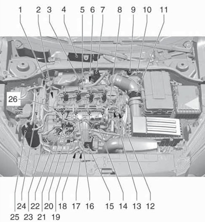
1.2a Location of the components of the power system in the engine compartment of diesel models 2.0 l TDI-CR (CFFB, CFGA, CLJA
1 Sensor "G505" pressure difference (only on CFFB and CFGB engines)
2 CMP sensor "G40"
3 Lambda probe "G39" with heating element "Z19" (only on CFFB and CFGB engines)
4 ECM "J623"
5 nozzles "N30" - "N33"
6 Check valve "N18" EGR, consists of an electrically controlled mechanical valve, regulating e / motor "V338" and potentiometer "G212"
7 Sensor "G581" boost pressure control position
8 Valve "N276" fuel pressure adjustment
9 Solenoid valve "N75" boost pressure adjustment
10 Sensor wiring connector #4 "G648" EGR temperature (CFFB and CFGB motors), sensor No. 1 "G235" EGR temperature (sensor "G507" temperature after turbocharger) and lambda probe 3
11 MAF sensor "G70"
12 ECT sensor "G62"
13 SKR sensor "G28"
14 Changeover valve "N345" EGR radiator
15 Throttle valve module "J338"
16 Glow plugs "Q10" - "Q13"
17 Coolant circulation pump no. 2 "V178"
18 Sensor "G31" boost pressure
19/20 Fuel line connection: to fuel rail/from fuel filter
21 Sensor "G81" fuel temperature
22 injection pump with metering valve "G290"
23 Sensor "G83" coolant temperature at the radiator outlet
24 Additional fuel pump "V393"
25 Sensor "G247" fuel pressure
26 Fuel filter
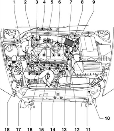
1.2b The location of the components of the engine power system 1.9 l (BXE code)
1 Glow plugs, 15 Nm
2 Activator "V157" intake manifold flaps
3 Inlet connection, with mechanical EGR valve
4 ECM "J248" with sensor "F96" heights
5 Pump injectors, under the cylinder head cover
6 Vacuum valve, for EGR radiator changeover flap
7 Sensor "G62" EATING
8 Cylinder block, with valve "N345" EGR radiator switching, EGR check valve "N18" and e / m valve "N75" fuel pressure adjustment
9 Sensor "G70" mass air flow
10 Sensor "G83" coolant temperature at the radiator outlet
11 Tandem pump
12 Central connector for unit injectors
13 Sensor "G81" fuel temperature
14 SKR sensor connector "G28"
15 Sensor connector 18
16 Vacuum reservoir
17 Sensor "G41" boost pressure with IAT sensor "G42"
18 CMP sensor "G40", under the timing belt cover
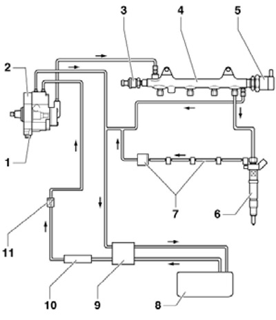
1.3 Diagram of the fuel supply system for diesel models 2.0 l TDI-CR (CFFB, CFGA, CLJA)
1 valve "N290" fuel dispenser, do not open
2 injection pump
3 Sensor "G247" fuel pressure
4 Fuel distribution line
5 Valve "N276" fuel pressure adjustment
6 Nozzle
7 Fuel return line (from injectors), with fuel pressure holding valve (at 2.0 bar)
8 Fuel tank
9 Fuel filter
10 Additional fuel pump "V393"
11 Sensor "G81" fuel temperature
The fuel supply module is an assembly of an electric priming pump and a fuel gauge, and also provides connections for fuel supply to an additional heater (see chapter 3). The electric priming pump is designed for continuous supply of fuel from the tank to the filter. The fuel level is displayed on the instrument cluster (see chapter "Controls and methods of operation").
The fuel filter protects the fuel supply system from contamination by water and other foreign particles and thus from premature wear. The fuel filter needs to be replaced periodically (see Section 23 of Chapter 1). A preheating valve is built into the filter, which prevents clogging of the filter with crystallizing paraffins at low ambient temperatures.
The additional fuel pump is designed to supply fuel from the low pressure circuit to the injection pump at a pressure of at least 5 bar, which is necessary for the operation of the injection pump in any modes. This vane type pump is controlled by a relay from the ECM. If the auxiliary pump fails, the engine power is reduced and it cannot be started.
A strainer and a ''G81' sensor are installed between the additional fuel pump and the injection pump" fuel temperature.
The injection pump, driven by the timing belt from the crankshaft, increases the fuel pressure to a maximum of 1800 bar and delivers it in one pipe to the fuel distribution line, where the fuel pressure is equalized for all injectors and monitored by a fuel pressure sensor.
High fuel pressure is regulated by the so-called "dual control algorithm": depending on the engine operating mode, either through the fuel pressure regulator valve or through the fuel metering valve. In this case, the valves are controlled by the engine control unit via a pulse-width modulated signal (PWM).
Adjustment through the fuel pressure regulator valve is carried out when the engine is started and to warm up the fuel. Good mixture formation in a combustion chamber with a short ignition delay requires a high fuel temperature. In order to quickly heat up the fuel when the engine is cold, the injection pump delivers and compresses more fuel than necessary, and the excess heated fuel is fed back through the pressure regulator valve and fuel return line. If the fuel pressure regulator fails, engine operation is impossible, because the pressure required for fuel injection cannot be built up.
Adjustment via the fuel metering valve is carried out with large injection volumes and high pressure in the fuel rail. This reduces the power consumption of the injection pump and prevents unnecessary heating of the fuel. If the fuel metering valve fails, the engine power is reduced, the engine control system operates in emergency mode.
Pressure fuel lines (metal tubes) manufactured with predetermined length and bending radii in the right places; install such fuel lines in such a way that they are not subject to any stress.
The injectors inject fuel at high pressure directly into the combustion chambers. The moment and duration of fuel injection are determined by the ECM using signals from various sensors (see section 2).
Excess fuel from the injectors is returned to the fuel tank through the injector return lines, pressure holding valve, and fuel pump. The fuel pressure holding valve is designed to maintain the pressure in the return lines of the injectors necessary for the operation of the injectors. Do not disconnect the fuel pressure holding valve while the engine is running to prevent damage to the injectors. The fuel return lines of the injectors are only replaced with the pressure holding valve. If the fuel retention valve and fuel return lines from the injectors have been replaced, run the engine at idle for approximately two minutes after starting the engine to purge air from the fuel system.
Fuel injection system with fuel rail "Common Rail", compared to an injection system with a distribution injection pump, has the following distinctive features:
- injection pressure can be freely selected and adapted to the respective engine operating conditions;
- high injection pressure (up to 1800 bar) creates conditions for good mixture formation;
- flexible batch injection process with multiple pre- and post-injections;
- low fuel consumption;
- low level of emission of harmful substances;
- smooth running engine.
injection system "Common Rail" involves a variety of injection control algorithms in order to adapt the pressure and injection process to the engine operating mode. At the same time, such a system fully meets the ever-increasing requirements for reducing fuel consumption, reducing the level of emissions of harmful substances and increasing the smoothness of the engine.
To improve engine starting performance, the fuel pump is activated for two seconds when the driver's door is opened to pre-pressurize the fuel system. Therefore, for safety during repairs without disconnecting the battery, remove the fuel pump relay fuse or disconnect the fuel delivery module connector.
Fuel Saving Tips
Driving style has a significant impact on fuel consumption. Below are some tips for saving fuel.
- Drive away immediately after starting the engine, even if it is in the cold (do not run a cold engine at high speeds and do not drive at high speed until the engine is warm).
- When stopping the car for more than 40 seconds, turn off the engine.
- Always drive in the maximum gear allowed for the given speed.
- When driving long distances, maintain a steady speed whenever possible. Avoid driving at high speeds, do not brake unnecessarily.
- Do not carry excess cargo on the vehicle.
- Check the air pressure in the tires, do not allow excessive pressure reduction.
