Caution: After disconnecting the fuel lines, plug the exposed holes to prevent dirt from entering the fuel supply system.
Engine 3.6 l
1. Details of the installation of the fuel distribution line and injectors are indicated on Ref. illustrations.
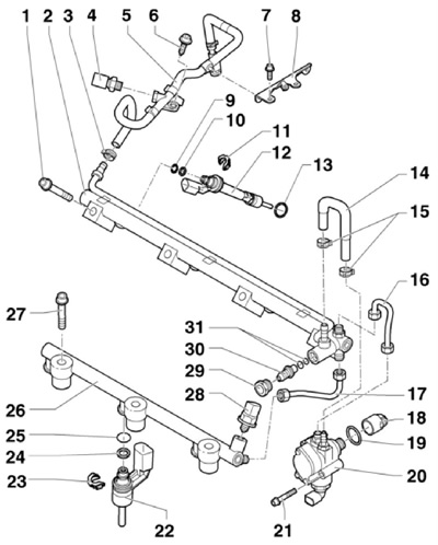
9.1 Installation details of the fuel rail and injectors (engine 3.6 l)
1 Bolt, to be replaced, 30 Nm, then retighten 90°
2 Fuel distribution line of cylinders No. 1,3,5; spring elements 11 must be replaced before installation
3, 15 Spring clamp
4 Sensor "G410" low fuel pressure, 15 Nm
5 Fuel supply hose (from the tank), with space for sensor 4; must be replaced, because damaged when removed
6, 7 Bolt, 8 Nm
8 Fuel hose support
9, 13, 19, 25, 31 O-ring, to be replaced
10, 24 Support washer
11 Spring element, replaced when line 2 is removed
12 Injector (on the example of cylinder No. 1)
14 Low fuel pressure hose, between injection pump and line 2; must be replaced, because damaged when removed
16 Fuel high pressure pipe, 40 Nm (to injection pump) and 28 Nm (to highway 2)
17 Connecting tube, 28 Nm
18 High-pressure fuel pump rod, lubricate with engine oil before installation
20 injection pump
21 Bolt, 10 Nm
22 Injector (on the example of cylinder No. 2)
23 Spring element, replaced when line is removed 26
26 Fuel distribution line of cylinders No. 2, 4, 6; spring elements 23 must be replaced before installation
27 Bolt, to be replaced, 30 Nm, then retighten 90°
28 Sensor "G247" fuel pressure, before installing, lubricate the front sealing cone and thread with engine oil
29 Plug, 22 Nm
30 Pressure relief valve, must be replaced after removal; pressed by hand with an 8 mm hexagon
2. Remove the upper part of the inlet pipeline (see Section 7) and injection pump (see Section 10).
3. Remove a connecting tube of a corresponding fuel distributive highway.
4. Turn out bolts of fastening of the bottom part of the inlet pipeline to a head of cylinders (see resist. illustration).
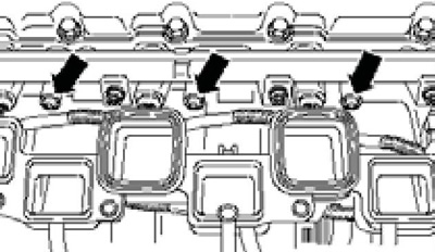
9.4 Bolts of fastening of the bottom part of the inlet pipeline
5. Remove the bolt (1 per resist. illustrations) dipstick guide tube, remove brackets (2) from the bottom of the intake manifold and remove the bolts (arrows) distribution line (the illustration shows the line of even cylinders). Carefully disconnect the distribution line from the injectors and remove the bottom of the intake manifold.
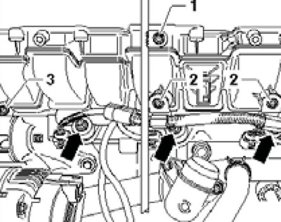
9.5 Removing the fuel rail
Note: If the injector has come out of the cylinder head, the Teflon ring must be replaced.
6. Installation is carried out in the reverse order. Use new injector springs and a new intake manifold bottom gasket.
Engine 1.4 l
7. The fuel distribution line is built into the bottom of the intake manifold. Details of the installation of injectors are indicated on the sopr. illustrations.
Petrol engines 1.8 and 2.0 l
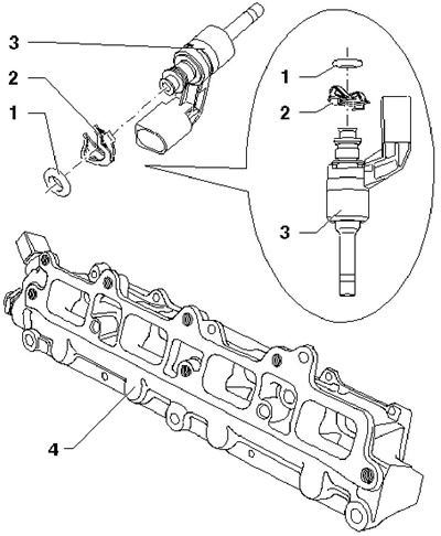
9.7 Details of installation of injectors and fuel rail/lower part of inlet pipe (engine 1.4 l)
1 O-ring, to be replaced, lightly lubricate with engine oil before installation
2 Spring element, after removal, replace part 4
3 Injector, after removal, replace the Teflon seal and support washer
8 Lower part of the intake pipe
8. Details of installation of components of system of injection of fuel are specified on sopr. illustrations.
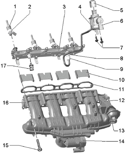
9.8 Installation details of the fuel injection system components (petrol models 1.8 and 2.0 l)
1 Injector, with replaceable Teflon seal and O-rings
2 support ring
3 Fuel distribution line
4 injection pump, with valve 6; the pressure line is fastened with a force of 17 Nm
5 Roller pusher
6 Solenoid valve "N276" fuel pressure adjustment
7 Injection pump mounting bolts, to be replaced, 10 Nm
8 Fuel supply connection, to be replaced, 25 Nm
9 Union nut, fuel supply line, 18 Nm
10 Airflow dampers
11 Gasket, to be replaced
12 Inlet pipeline
13 Vacuum block (regulator) intake manifold damper valve
14 Module "J338" throttle valve, motorized "G186" and position sensors No. 1 "G187" and #2 "G188"
15 Intake manifold bolts, 3 Nm, then 9 Nm
16 Sensor "G336" intake manifold flap position, adapt ECM when replacing
17 Sensor "G247" fuel pressure, 25 Nm, lubricate the threads with engine oil before tightening
9. The fuel distribution line is removed together with the inlet pipeline, after which they can be separated from each other (see Section 7). Details of the installation of injectors are indicated on the sopr. illustrations.
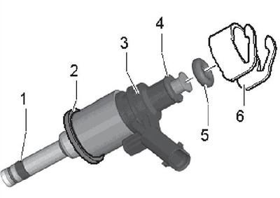
9.9 Injector components
1 Combustion chamber Teflon seal, replaceable, installed without lubrication
2 Intermediate ring, cone must face valve
3 Injector
4 support ring
5 O-ring, to be replaced, lubricate with engine oil before installation
6 Support element (for transmitting force to the fuel rail and holding the injector in the cylinder head)
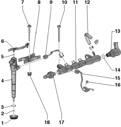
9.10 Installation details of the fuel injection system components of 2.0L diesel engines (CFFB, CFGB and CLJA), except for injection pump
1 Seal, in cylinder head cover
2 Copper washer, replaceable
3, 5, 14 O-ring, to be replaced
4 Nozzle
6 Fuel return line, from injectors to fuel tank, with 2.0 bar retention valve, do not disassemble
7 Bolt, to be replaced, 8 Nm, then retighten 180°
8 Retaining part, installed only in its original place
9 Pressure line, between line 11 and nozzle,
15 Nm, then tighten to 60°
10 Bolt, 22 Nm
11 Fuel distribution line
12 Fuel return hose
13 Valve "N276" fuel pressure regulator, 80 Nm, must be replaced after removal
15 Pressure line, between high pressure pump and line 11, 15 Nm, then tighten to an angle of 60'
16 Bolt, 8 Nm
17 Sensor "G247" fuel pressure, 100 Nm, must be replaced after removal
18 Sleeve in the cylinder head cover
Diesel engines 2.0 l (CFFB, CFGB and CLJA)
22. Details of the installation of the components of the fuel injection system are indicated on Ref. illustrations. Attention: After removing the components of the fuel supply system, before starting the engine, the air must be bled from the system (see Section 3).
Diesel engines 1.9 l (WHE, BLS)
23. Details of the installation of the unit injector are indicated on the resist. illustrations. After removing the unit injector, all its sealing rings must be replaced.
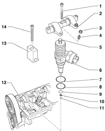
9.23 Parts for installing the unit injector
1 Bolt, to be replaced, 20 Nm, then retighten 90°
2 Awn of rocker arms, with rocker arms
3 Locknut, 30 Nm
4 Adjusting bolt; must be replaced when installing a new unit injector
5 Articulating rod, to be replaced
6 pump nozzle
7-9 O-ring, to be replaced
10 Thermal washer, to be replaced
11 Retaining ring
12 Cylinder head
13 Clamp
14 Bolt, to be replaced, 12 Nm, then tighten 270°
