Engine 1.4 l
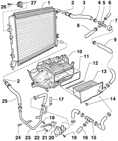
1. Details of the installation of the intercooler are indicated on Ref. illustrations. The intercooler can only be removed after the intake manifold has been removed. The intercooler radiator can be removed after removing the main radiator (see chapter 3) and front bumper covers (see chapter 11).

6.1 Intercooler installation details (engine 1.4 l)
1 Additional radiator for intercooler, with upper and lower sealing strips
2 O-ring
3 Upper coolant hose
4 Spring band clamp
5 Connecting tube
6 Coolant hose, to expansion tank
7 Protective sleeve
8 Coolant hose, to turbocharger
9, 16, 17 coolant hose
10 Inlet pipeline
11 Gasket
12 Sealing strip
13 Intercooler
14 Bolt, 7 Nm
15 Connecting tube
18, 19, 24 Bolt, 8 Nm
20 Coolant circulation pump "V50"
21 Bracket
22 Bolt, 20 Nm
23 Coolant pipe
25 Lower coolant hose
26 Bolt, 7 Nm
27 Intercooler radiator support
Petrol engines 1.8 l
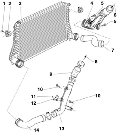
2. Details of installation of the intercooler are indicated on Ref. illustrations.

6.2 Intercooler installation details (petrol engines 1.8 and 2.0 l)
1, 11 Bolt, 5 Nm
2 Intercooler support
3 Intercooler
4 Charge air pipe
5, 10 Bolt, 8 Nm
6 From turbocharger
7, 9 charge air hose
8 To throttle module
12 Sensor "G31" boost pressure
13, 14 Charge air hose
3. Remove the radiator of the engine cooling system (see chapter 3).
4. Remove the front bumper cover (see chapter 11).
5. Disconnect the left and right air pressure hoses from the intercooler.
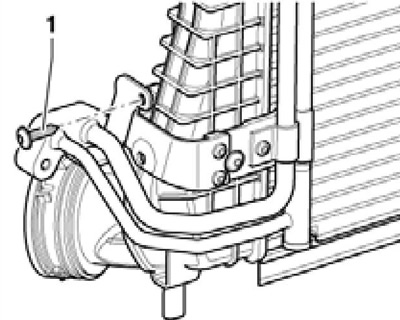
6. Turn out bolts (2 in Illustration 3.11 of Chapter 3) refrigeration condenser mountings and bolts (1) intercooler. Do not disconnect the refrigerant lines, do not bend or pull them.
7. With an assistant, press the intercooler away from the hood latch holder so that you can access the bolt (1 per resist. illustrations) refrigerant lines. Remove this bolt and carefully remove the intercooler downwards.

6.7 Refrigerant line bolt
8. Installation is carried out in the reverse order. Use new o-rings.
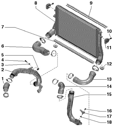
Diesel engines 2.0 l (CFFB, CFGB and CLJA)

6.9 Intercooler installation details (2.0L CFFB, CFGB and CLJA engines)
1, 14 Connecting hose
2 Left charge air pipe
3 bushing
4 Bolt, 10 Nm
5 Rubber bush
6 Left charge air hose
7 Bottom seal
8 Intercooler
9 Top seal
10, 16 Bolt, 5 Nm
11 Side support
12 Bottom support
13 Right charge air hose
15 Right charge air pipe
17 Sensor "G31" boost pressure with IAT sensor "G42"
18 O-ring, to be replaced
15. Details of installation of the intercooler are indicated on Ref. illustrations.
