On-board self-diagnosis system (OBD)
1. The models described in this manual are equipped with an on-board diagnostic system for European countries (EOBD).
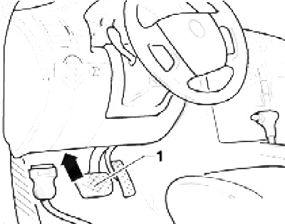
2. Reading OBD system data and clearing the processor memory is performed using special diagnostic equipment connected to the diagnostic connector (DLC), - see resist. illustration. It would be wise to entrust the procedures for reading / erasing DTCs and clearing the ECM memory to a service station. The diagnostic K-line is used only for diagnosing the engine management system and DSG transmission (see illustration 1.1). Diagnosis of the remaining control units is carried out via the CAN bus.

4.2 Connecting the diagnostic tool
Information about diagnostic tools
3. Checking the correct functioning of the components of the injection systems and the reduction of exhaust gas toxicity is carried out using a universal digital meter (multimeter). The use of a digital meter is preferred for several reasons. Firstly, it is quite difficult for analog devices to (sometimes it's impossible), determine the result of the indication with an accuracy of hundredths and thousandths, while when examining circuits that include electronic components, such accuracy is of particular importance. The second, no less important, reason is the fact that the internal circuit of the digital multimeter has a fairly high impedance. Since the voltmeter is connected in parallel to the circuit under test, the measurement accuracy is higher, the smaller the current will pass through the device itself. This factor is not significant when measuring relatively high voltage values (9:12 a.m), however, it becomes decisive in the diagnosis of elements that produce low-voltage signals, such as, for example, a lambda probe, where we are talking about measuring fractions of a volt.
4. Parallel monitoring of signal parameters, resistances and voltages in all control circuits is possible using a splitter connected in series to the engine control unit connector. At the same time, with the engine turned off or running, or while the car is moving, the signal parameters are measured at the splitter terminals, from which a conclusion is made about possible defects.
5. For diagnostics of electronic systems, it is recommended to use the diagnostic complex VAS5051 B, or the diagnostic tester VAS5052 or VAS5053. In addition, for this purpose, you can use a specialized automotive diagnostic computer, specially designed for the complete diagnosis of most systems of modern cars (e.g. ADC2000 from Launch HiTech). For this purpose, you can also use scanners and specialized diagnostic analyzers, for example, FDS 2000, Bosch FSA 560 (www.bosch.de) or a regular personal computer with a special adapter, cable and OBD II browser installed.
Note: A free version of the OBD II browser can also be "download" from the site of the compilers of this Guide: http://arus.spb.ru.
6. Some scanners, in addition to the usual diagnostic operations, allow, when connected to a personal computer, to print circuit diagrams of electrical equipment stored in the memory of the control unit (if any), program the anti-theft system, observe the signals in the car circuits in real time.
