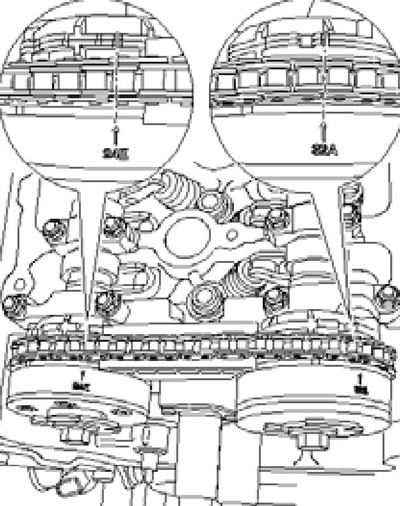
Note: From 11.2008, the exhaust camshaft phase adjuster is installed "32A" with plastic cover.
1. Remove the soundproofing under the engine compartment and the locker of the right front wheel arch (see chapter 11).
2. Remove the cylinder head cover (see Section 9).
3. Turn the crankshaft with support T10172 clockwise until the TDC marks are aligned (see illustration 9.29a). In this case, the camshaft cams for cylinder No. 1 must face each other (see illustration 9.29b).
4. Install template T10068A in the slots of both shafts (see illustration 9.45). Note: Due to the operation of the timing adjusters, the slots may be located with some deviation from the horizontal, therefore, to install the template, it may be necessary to rotate them slightly by the flats (see illustration 9.32).
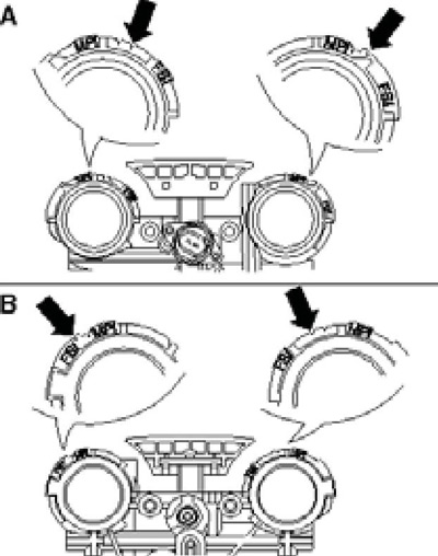
5. Make sure that the marks on the timing adjusters are aligned with the right risks on the timing adjuster housing (see resist. illustrations).

10.5a TDC marks on the timing regulators

10.5b Marks on timing housing on flywheel sides (A) and pulley (IN)
Note: Slight label mismatch is allowed "32A" with the associated risk. Ignore the position of the copper-colored timing chain links.
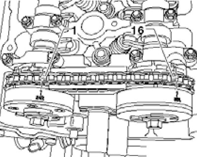
6. There should be 16 timing chain rollers between the marks on the adjusters (see resist. illustration).

10.6 Chain rollers between the marks on the adjusters
7. If the above conditions are met, install the cylinder head cover and upper intake manifold. Otherwise, adjust the timing (see Section 11).
