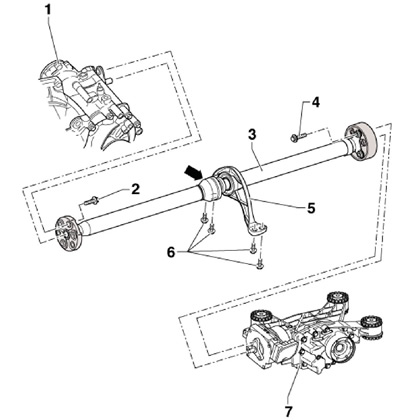
7.1 PTO shaft installation details
1 corner drive
2 Bolts M 10x30, 3 pcs., 60 Nm
3 Cardan shaft, during installation, bearing 5 must be behind the joint (arrow)
4 Bolts M 10x45, 3 pcs., 60 Nm
5 Intermediate bearing, must be aligned without tension
6 Bolt, 25 Nm
7 Rear final drive
2. Before removing, mark the relative position of all parts relative to each other, so that they can then be installed in the same position. In this way, imbalances that cause noise can be avoided.
3. Remove the sound insulation under the engine compartment (see chapter 11).
4. Remove the entire exhaust system (see chapter 4).
5. Support the propeller shaft with a transmission jack, placing wooden blocks between them (And on the opposite illustrations), and secure the shaft to the jack with suitable straps. Remove the bolts (arrows) and remove the heat shield under the driveshaft.
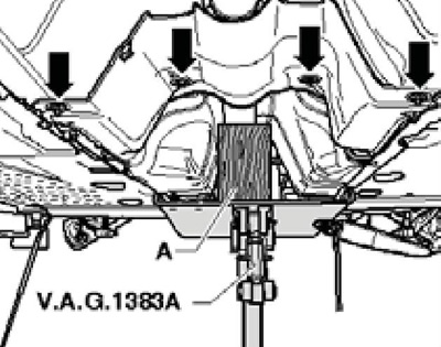
7.5 Removing the PTO shaft heat shield
6. Mark the position of the cardan shaft with the flexible disk relative to the output flange of the corner gear, and then fasten the cardan shaft to the output flange of the corner gear (see illustration 5.19 Chapter 6).
7. Remove the rocker from the transmission by removing the bolts (B and C in Figure 5.20 of Chapter 6).
8. After removing the rocker from the manual transmission, the power unit leans forward slightly, so be careful not to damage the gasket (see illustration 5.21 of chapter 6) in the driveshaft flange.
9. Check for color marks on the flexible disk of the cardan shaft and on the flange of the Haldex coupling (see resist. illustration). Apply these marks as needed.
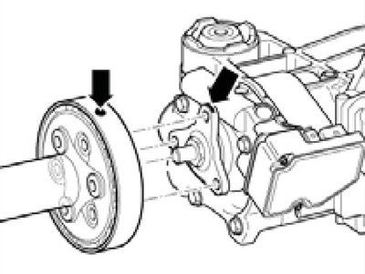
7.9 Markings on the cardan shaft and on the flange of the Haldex coupling
10. Turn out bolts of fastening of the propeller shaft to the Haldex coupling flange (see resist. illustration).
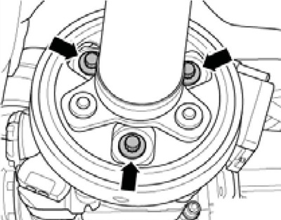
7.10 Bolts for fastening the cardan shaft to the Haldex coupling
11. Ask an assistant to hold the driveshaft. Turn out bolts of fastening of the intermediate bearing (see resist. illustration) and move the shaft forward while slightly pushing the power unit forward. Then pull the driveshaft off the centering pin on the rear final drive and pull the shaft off the centering pin on the bevel gear. Do not tilt the cardan shaft, slide it horizontally from the centering studs so as not to damage the gaskets (see illustration 5.21 of chapter 6) in the flanges of the cardan shaft. After removal, do not bend the cardan shaft.
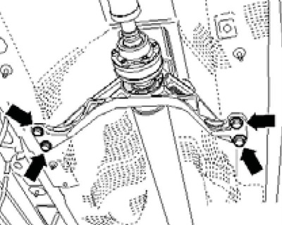
7.11 Fastening of the intermediate bearing of the cardan shaft
12. Installation is carried out in the reverse order. Install the shaft so that all the marks made when removing the marks coincide.
