Note: Depending on the installed transmission, one of five front drive shaft options can be installed: "VL100", "VL107", "AAR3300i", "RO104" or "R03700". Illustrations explaining the differences between the front drive shafts are presented in Section 5.
Front drive shafts
1. Remove the hub bolt (see section 2) and remove the front wheel.
2. Remove the sound insulation under the engine compartment (see chapter 11).
3. If available, remove the CV joint heat shield from the engine.
4. Turn out bolts of fastening of a power shaft to a flange shaft of transmission.
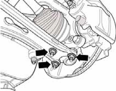
5. Give nuts (see resist. illustration) and separate the steering knuckle together with the ball joint from the suspension arm.

4.5 Ball joint nuts
6. Pull the drive shaft out of the hub by hand.
7. Remove paint residue and rust from the threads and splines of the outer CV joint. Insert the outer CV joint into the splines of the front wheel hub as far as possible.
8. Tighten the new nuts securing the suspension arm to the ball joint with a force of 100 Nm.
9. Position the inner CV joint in place and tighten its new bolts diagonally to 10 Nm, and then tighten them to 40 Nm (M8 bolts) or 70 Nm (M10 bolts).
10. Install soundproofing.
11. Tighten the hub bolt following the sequence in Section 2.
Rear drive shafts
12. Remove the hub bolt (see section 2) and remove the rear wheel.
13. Turn out a bolt (1 in illustration 3.20) guide arm mounting and bolt (3) fastening the lower arm of the rear suspension to the holder of the hub assembly (4).
14. Turn out the lower bolt (see illustration 3.19) shock absorber mountings.
15. Give fixture of a power shaft on a flange of back differential.
16. Tilt the hub assembly holder outward and remove the drive shaft by pulling it out of the inner splines.
17. Installation is carried out in the reverse order. Tighten the bolts securing the drive shaft to the rear differential flange diagonally, first to 10 Nm, then tighten them to 20 Nm, and finally tighten them by 180°.
