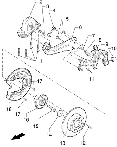
3.1a Installation details of the rear hub assembly and rear suspension trailing arm (FWD models)
Arrow Direction of movement
1 Bolt, to be replaced, 50 Nm, then retighten 45°
2 Support bracket
3, 5 Bolts, to be replaced, 90 Nm, then retighten by 90°
4 The stabilizer bar of the transverse stability
6 Trailing arm
7 Sensor mounting bolt 8.8 Nm
8 ABS wheel sensor, before installation, clean the inner surface of the mounting hole and apply G000 650 grease to it
9 Hub assembly holder
10 Rubber bushing
11 Self-locking nut, replaceable, 45 Nm
12 Brake disc bolt, 4 Nm
13 Brake disc
14 Plug of bolt 15, to be replaced
15 Hub bolt, to be replaced, 180 Nm, then retighten 180°
16 Hub assembly (hub with bearing), with integrated sensor rotor 8, no repairs or adjustments
17 Shield bolt 18, 12 Nm
18 Brake guard
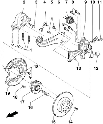
3.1b Rear hub assembly and rear trailing arm installation details (AWD models)
Arrow Direction of movement
1 Bolts, to be replaced, 50 Nm, then retighten by 45°
2 Support bracket
3 Bolt, to be replaced, 90 Nm, then retighten 90°
4 The stabilizer bar of the transverse stability
5 Bolts, to be replaced, 90 Nm, then retighten by 45°
6 Trailing arm
7 Drive shaft
8 Bolts, to be replaced, 70 Nm, then retighten by 90°
9 Hub assembly holder
10 ABS wheel sensor, before installation, clean the inner surface of the mounting hole and apply G000 650 grease to it
11 Sensor mounting bolt 10.8 Nm
12 Rubber bushing
13 Self-locking nut, replaceable, 40 Nm
14 Brake disc bolt, 4 Nm
15 Brake disc
16 Hub bolt, to be replaced, 70 Nm, then retighten by 90°
17 Hub assembly (hub with bearing), with built-in sensor rotor 10, repair and adjustment not provided
18 Shield bolts 19, 12 Nm
19 Brake guard
Hub assembly of FWD models
2. Jack up the vehicle and place it on jack stands. Remove the rear wheel.
3. Pry off the hub bolt cover (see resist. illustration) and remove it with pliers.
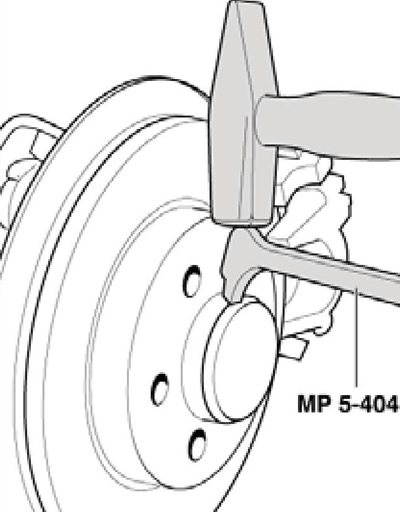
3.3 Separating the hub bolt cover
4. Remove the caliper with anchor bracket and hang them on the body parts on the wire without disconnecting the brake fluid hose (see chapter 9). In this case, the hose should not be tense.
5. Turn out a bolt and remove a brake disk (see chapter 9).
6. Remove the hub bolt (15 in illustration 3.1a) and remove the hub assembly from the spindle.
7. Carefully slide the hub assembly onto the spindle without tilting.
8. Tighten the new hub bolt and install its new cap with a suitable bushing.
9. Further installation is carried out in the reverse order.
Hub assembly of AWD models
10. Remove the rear suspension spring (see chapter 10).
11. Remove the drive shaft (see Section 4).
12. Remove the caliper with anchor bracket and hang them on the body parts on the wire without disconnecting the brake fluid hose (see chapter 9). In this case, the hose should not be tense.
13. Turn out a bolt and remove a brake disk (see chapter 9). Remove the brake shield.
14. Turn out bolts (2 to resist. illustrations) and remove the hub assembly from its holder.
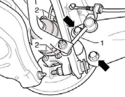
3.14 Bolts (2) fastening of the hub rear assembly and its holder (arrows) on AWD models
15. Installation is carried out in the reverse order. When tightening the hub bolt, take into account the features indicated in the corresponding subsection Section 2.
Hub assembly holder
16. Remove the rear suspension spring (see chapter 10).
17. Remove hub assembly (see relevant subsection above).
18. Remove the brake shield and ABS wheel sensor (see chapter 9).
19. Turn out the bottom bolt of fastening of the shock-absorber (see resist. illustration).
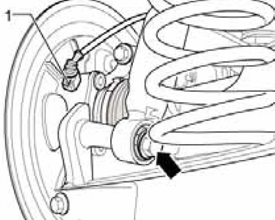
3.19 Shock absorber lower bolt
20. Give the nut (arrow on resist illustrations) stabilizer struts, remove the bolt (1) fastening the guide arm to the subframe, as well as bolts (2 and 3) fastening, respectively, of the upper and lower levers to the holder of the hub assembly (4).
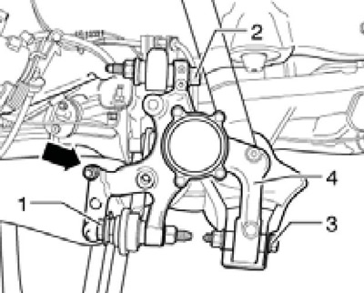
3.20 Fastening the suspension parts in the area of the hub assembly holder (AWD models)
21. Holding the holder of the hub assembly, remove the bolts (arrows in illustration 3.14) its fasteners and remove the holder from the thread of the stabilizer strut (1).
22. The threaded connections of the trailing arm and the hub assembly holder may only be tightened after all suspension components of the corresponding wheel have been installed (especially the spring and shock absorber). For tightening, the suspension must be in the unloaded position. Only then move the trailing arm and hub assembly holder to the desired position (arrows on resist. illustrations). Stick to the following sequence.
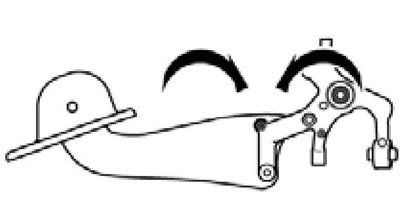
3.22 Moving the hub assembly holder and trailing arm
23. Screw in, but do not tighten the bolts (1 and 2 on resist. illustrations) fastening the holder of the hub assembly, respectively, to the trailing arm and stabilizer bar.
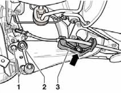
3.23 Mounting bracket for hub assembly
24. Screw in but do not tighten the guide arm fasteners (1 in illustrations 3.20a-b), as well as the upper and lower arms (2 and 3) to the holder of the hub assembly.
25. Install hub assembly (see relevant subsection above) and brake shield.
26. Screw in, but do not tighten the lower shock absorber bolt (see illustration 3.19).
27. Install the suspension spring, set the suspension to the unloaded position.
28. Tighten the bolt (1 per illustration 3.20) guide arm and bolt (3) lower lever.
29. Tighten the bolt (1 per resist. illustrations) upper lever. Washer (2) must be installed so that between it and the plate (3) there was a gap.
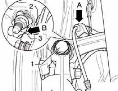
3.29a Upper arm bolt (FWD models)
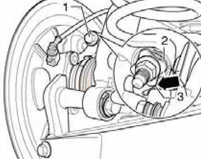
3.29b Upper arm bolt (AWD models)
30. Tighten the lower shock absorber bolt and remove the suspension holding devices in the unloaded position.
31. Tighten the bolts (1 in illustration 3.23) trailing arm, making sure it is in the correct position relative to the hub assembly holder. tighten the nut (2) fastening the stabilizer bar to the holder of the hub assembly.
32. Install the ABS wheel sensor, brake disc and anchor bracket with caliper (see chapter 9).
33. Adjust wheel alignment (see chapter 10).
