22. Valve clearance adjustment is performed on a cold engine. Disconnect the crankcase breather hose and remove the valve cover (Section 2). It may also be helpful to remove the spark plugs to make the crankshaft turn more easily.
23. It is important that when adjusting the gap, the adjustable valve lifter is in the lower phase of the stroke. This can be done by numbering the valves from left to right and adjusting in the following order (do not turn the crankshaft more than necessary).
| Valve fully open | adjustable valve |
| № 8 | № / (high school graduation) |
| № 6 | № 3 (inlet) |
| № 4 | № 5 (high school graduation) |
| № 7 | № 2 (inlet) |
| № 1 | № 8 (high school graduation) |
| № 3 | № 6 (inlet) |
| № 5 | № 4 (high school graduation) |
| № 2 | № 7 (inlet) |
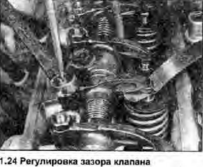
24. The correct valve clearances are indicated in Specifications at the beginning of this Section. Loosen the hex locknut while holding the ball stud with a screwdriver. Between the valve stem head and the rocker arm, insert a feeler gauge equal to the thickness specified in Specifications valve clearance. Turn the ball stud until the feeler gauge is pinched (photo). Then, while holding the ball stud in the correct position, tighten the locknut and recheck the clearance. Turn the crankshaft and repeat this procedure on the remaining valves.

25. Reinstall the valve cover, crankcase breather hose, and spark plugs.
