Note: See Warnings given in Chapter 1 of this section before starting work.
Removing
1. Drain the liquid from the cooling system (see section 1). If the antifreeze cannot be replaced, collect the drained fluid in a clean container.
2. Loosen the clamps and separate the coolant supply and return hoses from the connecting pipes with the control valve, which are located at the end of the matrix (on the right side of the heater block). Be prepared for some liquid to come out.
3. Loosen the pinch screw and separate the control cable from the control valve lever.
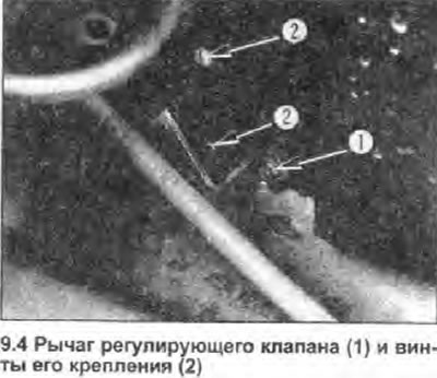
4. Loosen the four fixing screws (see photo) and remove the control valve.

Installation
5. Install in reverse order. Make sure the mating surfaces are clean and install a new O-ring. Make sure the valve assembly is properly oriented when installed in the heater matrix (lever should be positioned as shown). Make sure the lever/cable adjustment allows the valve to fully open and close.
6. Finally, fill the cooling system and check the heater hose connections for leaks.
